EasyManua.ls Logo

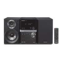
Panasonic SA-PM33EE User Manual

Panasonic SA-PM33EE
94 pages
To Next Page IconTo Next Page
Page #1 background imageLoading...
Page #1 background image
RMS OUTPUT POWER both channel driven simultaneously
10% total harmonic distortion 20 W per channel (6 )
Input impedance
MUSIC PORT 250 mV 12 k
Output impedance
HEADPHONE 16 to 32
Phone jack
Terminal Stereo, 3.5 mm
Music Port input jack
Terminal Stereo, 3.5 mm
n FM Tuner Section
Frequency range 87.50 to 108.00 MHz
(50 kHz step)
Sensitivity 3.8 µV (IHF)
S/N 26 dB 1.2 µV
A
ntenna terminals 75 (unbalanced)
Preset station FM 15 stations
AM 15 stations
n AM Tuner Section
Frequency range 522 to 1629 kHz
(9 kHz steps)
520 to 1630 kHz
(10 kHz steps)
Sensitivity
© 2006 Matsushita Electric Industrial Co. Ltd.. All
rights reserved. Unauthorized copying and
distribution is a violation of law.
SA-PM33EE
Colour
(S)... Silver Type
S/N 20 dB (at 999 kHz) 1122 µV/m
n Cassette Deck Section
Track system 4-track, 2-channel
Heads
Record/playback Solid permalloy head
Erasure Double gap ferrite head
Motor DC servo motor
Recording system AC bias 100 kHz
Erase system AC erase 100 kHz
Tape speed 4.8 cm/s
Overall frequency response (+3 dB, -6 dB) at DECK OUT
Normal 35 Hz to 14 kHz
S/N RATIO 47 dB (A weighted)
Wow and flutter 0.08% (WRMS)
Fast-forward and rewind time Approx. 120 seconds with C-60
cassette tape
n CD Section
Disc played [8 cm or 12 cm]
(1) CD-Audio (CD-DA)
(2) CD-R/RW (CD-DA, MP3 formatted disc)
(3) MP3
Sampling frequency
CD 44.1 kHz
MP3 32 kHz, 44.1 kHz, 48 kHz
CD Stereo System
Specification
ORDER NO. MD0603074C3

Table of Contents

Question and Answer IconNeed help?

Do you have a question about the Panasonic SA-PM33EE and is the answer not in the manual?

Panasonic SA-PM33EE Specifications

General IconGeneral
Power Output20 W
Number of Speakers2
Disc PlaybackCD, CD-R/RW
TunerFM/AM
BluetoothNo
USB PlaybackYes
Speaker Type2-way speakers
Preset Stations30
ConnectivityAUX
TypeMicro Hi-Fi System

Summary

Safety Precautions and Guidelines

General Guidelines and Leakage Current Checks

Covers general safety rules and specific leakage current testing procedures.

Repair and Adjustment Precautions

Protection Circuitry Operation

Electrostatic Discharge (ESD) Prevention

Laser Diode Safety Precautions

Traverse Deck Handling Precautions

Lead-Free Solder Handling

Self-Diagnosis and Special Modes

Special Mode Table

Reference table for special modes, their descriptions, FL display, and required key operations.

Cassette Mechanism Self-Diagnosis

EEPROM Checksum and ROM Correction

Procedure to check microprocessor firmware version and EEPROM checksum for ROM correction.

CD to Tape Recording Test

Tape Recording and Playing Test

Procedure to check the tape recording and playback functions, including FWD play and tape opening.

TPS Inspection Procedure

Error Code Table for Self-Diagnosis

Assembly and Disassembly Procedures

Disassembly Flow Chart

Main Parts Location Diagram

Power PCB Disassembly

CD Mechanism Disassembly

Traverse Unit, Gear, and Cam Disassembly

Optical Pickup Disassembly

Traverse Gear A and B Disassembly

Pinch Roller and Head Block Disassembly

Motor and Belt Disassembly

Deck Mechanism PCB Disassembly

Cassette Tape Jam Handling

Service Positions Overview

CD Mechanism PCB Checking and Repairing

Deck Mechanism Unit Operation Checks

Cassette Deck Measurement and Adjustments

Tape Speed Adjustment

Procedure for adjusting the tape speed to the specified output level using a frequency indicator and motor screw.

Bias Voltage Check

Bias Frequency Check

Voltage Measurement - CD Servo PCB

Voltage Measurement - Main PCB

Voltage Measurement - Panel PCB

Voltage Measurement - Power PCB

Voltage Measurement - Deck PCB

Voltage Measurement - Deck Mechanism PCB

Waveform Measurements - CD Servo Signals

Waveform Measurements - Microprocessor and Control Signals

Wiring Connection Diagram

Block Diagram - CD Signal Path

Main Circuit Schematic Diagram

Power Circuit Schematic Diagram

CD Servo Circuit Schematic

Main Circuit and Tuner Extent Circuit Schematic

Main Circuit Schematic Details

Deck Circuit, Mechanism, and Tape Eject Schematics

Power Circuit Schematic

CD Servo PCB Layout

Deck, Deck Mechanism, and Tape Eject PCB Layouts

Illustration of ICs, Transistors, and Diodes

IC7001 Terminal Functions

IC7002 and IC803 Terminal Functions

IC7002 Terminal Functions

Pin details for IC7002, the 4-channel drive IC, specifying I/O and function for each pin.

IC803 Terminal Functions

Pin details for IC803, the microprocessor, specifying I/O and function for each pin.

IC803 Microprocessor Terminal Functions (Continued)

Troubleshooting Flowchart - CD Section

Troubleshooting Flowchart - CD Section (Continued)

Cassette Deck and Traverse Deck Part Locations

Replacement Parts List - Cabinet and Chassis

Replacement Parts List - Traverse Deck Parts

Replacement Parts List - Integrated Circuits

List of integrated circuits used in the unit, including IC numbers, part names, and descriptions.

Replacement Parts List - Transistors and Diodes

Related product manuals