Do you have a question about the Panasonic SA-PM08 and is the answer not in the manual?
Details order number, system type, color, and regional variations.
Covers amplifier power, tuner ranges, and disc playback details.
Provides power, dimensions, mass, notes, and Dolby licensing information.
Explains protection circuitry and precautions for handling the traverse deck.
Instructions for handling the optical pickup and preventing electrostatic discharge.
Steps for traverse deck replacement and laser safety warnings.
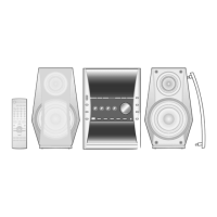
Identifies controls on the main unit and the remote control layout.
Procedure for checking main, power supply, and system control P.C.B.s.
Steps for checking the DVD module (1) P.C.B. and the mic echo P.C.B.
Procedures for checking DVD Module (2) and Power AMP P.C.B.s.
Detailed steps for replacing the traverse deck assembly.
Steps for replacing the traverse motor, optical pickup, and spindle motor assemblies.
Procedure for replacing the belt, loading motor assembly, and loading switch.
Steps for replacing the lamp assembly, shutter panel, and rack components.
Procedure for replacing transfer gears, belts, pulleys, and motors.
Detailed steps for replacing the power integrated circuit.
Notes on schematic diagrams and illustrations of ICs, transistors, and diodes.
Details terminal functions for IC501 and lists other technical diagrams.
Safety notices for components, part marking conventions, and stock retention.
Exploded view illustrating the location of cabinet parts.
Exploded view showing the location of parts within the CD mechanism.
Diagram illustrating the packaging of the product.
Component placement diagrams for Power, System Control, Lamp, and Operation P.C.B.s.
Component placement diagrams for DVD Modules, MIC Amp, and Headphone/Mic Jack P.C.B.s.
Schematic diagrams detailing the system control and operation circuits.
Schematic diagrams for power amplifier and loading motor circuits.
Schematic diagrams for MIC amplifier and headphone/mic jack circuits.
Detailed schematics of signal selector and buffer amplifier ICs.
Schematics for signal selector ICs and associated attenuator circuits.
Schematics for electronic volume control and interface ICs.
Schematics for buffer amplifier and muting circuits.
Schematic detailing the power amplifier stages and motor driver circuits.
Schematic showing power amplifier stages and protection components.
Detailed schematic of the power supply unit, including regulators and transformers.
Schematic of regulator, control, and relay circuits within the power supply.
Schematic of the FM/AM tuner unit, including PLL synthesizer.
Schematic of the IF amplifier, detector, and mixer circuits.
Detailed schematics of IF amplifier, detector, and mixer circuits.
Visual identification and pin counts for key ICs, transistors, and diodes.
Component placement diagrams for DVD Module (1) and (2) P.C.B.s.
Diagram showing how major P.C.B.s and modules interconnect.
| Brand | Panasonic |
|---|---|
| Model | SA-PM08 |
| Category | Stereo System |
| Language | English |