not touch the legs of ICor LSI with the fingers directly.
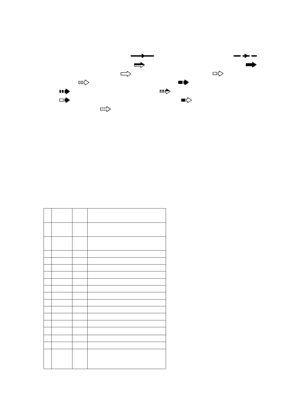
- Voltage and signal line / : Positive voltage line / :
Negative voltage line / : Video/audio signal line / :
Video signal line / : Audio signal line / : FM signal
line / : FM OSC signal line / : AM signal line /
: AM OSC signal line / : Sub woofer signal line /
: CenterSP drive signal line / : Surround SP. drive
signal line / : MIC signal line
10.2. Schematic Diagram
11. Printed Circuit Board Diagram
12. Block Diagram
13. Wiring Connection Diagram
14. Terminal Function of ICs
14.1. IC501 (MN101C38CRC1): / System Control and LCD driver
Pin
No.
Terminal
Name
I/O Function
1-
4
COM3-
/ COM0
O LCD Common signal output
5-
7
VLC3- /
VLC1
I LCD Bias
8 Vdd Power supply
9 OSC2 O Main oscillator output signal
10 OSC1 I Main oscillator input signal
11 GND Ground
12 XI I Sub oscillator input signal
13 XO O Sub oscillator output signal
14 GND Ground
15 VREF- A/D converter reference ground
16 KEY1 I Key1 input signal
17 KEY2 I Key2 input signal
18 NC N.C.
19
PWRDET
I POWR DETECT
20 NC N.C.
21 DES I Destination
22 DISC
OPN
SW
I DVD/CD tray open switch
29