EasyManua.ls Logo

Panasonic SA-PMX70 User Manual

Panasonic SA-PMX70
65 pages
To Next Page IconTo Next Page
Page #1 background imageLoading...
Page #1 background image
© Panasonic Corporation 2015. All rights reserved.
Unauthorized copying and distribution is a violation of
law.
PSG1502005CE
CD Stereo System
Model No. SA-PMX70EG
Product Color: (S)...Silver Type
(K)... Black Type
TABLE OF CONTENTS
PAGE PAGE
1 Safety Precautions----------------------------------------------- 3
1.1. General Guidelines---------------------------------------- 3
1.2. Before Repair and Adjustment ------------------------- 4
1.3. Protection Circuitry---------------------------------------- 4
1.4. Caution For Fuse Replacement------------------------ 4
1.5. Safety Part Information----------------------------------- 4
2 Warning-------------------------------------------------------------- 5
2.1. Prevention of Electrostatic Discharge (ESD)
to Electrostatically Sensitive (ES) Devices---------- 5
2.2. Precaution of Laser Diode------------------------------- 6
2.3. Service caution based on Legal restrictions --------7
2.4. Handling Precaution for Traverse Unit----------------8
3 Service Navigation --------------------------------------------- 10
3.1. Service Information-------------------------------------- 10
4 Specifications---------------------------------------------------- 11
5 Location of Controls and Components------------------ 12
5.1. Main Unit & Remote Control Key Button
Operations ------------------------------------------------- 12
6 Service Mode----------------------------------------------------- 13
6.1. Service Mode Table ------------------------------------- 13
Notes: Please refer to the Original Service Manual for :
O CD Mechanism Unit (BRS12C), Order No. PSG1303059AE
O Speaker system SB-PMX70EG-K, Order No. PSG1502006CE

Table of Contents

Question and Answer IconNeed help?

Do you have a question about the Panasonic SA-PMX70 and is the answer not in the manual?

Panasonic SA-PMX70 Specifications

General IconGeneral
Power Output120 W
Speaker Configuration2.0
Speaker type2-way
Tweeter diameter2.5 cm
Woofer diameter10 cm
Signal-to-Noise Ratio80 dB
Input Sensitivity500 mV
Speaker Impedance6 Ω
Impedance6 Ω
BluetoothYes
Bluetooth version4.2
CD PlayerYes
Optical disc playerYes
Disc types supportedCD, CD-R, CD-RW
FM TunerYes
RadioYes
Radio bands supportedFM
Preset stations quantity30
USB PortYes
Headphone outputs1
Headphone connectivity3.5 mm
Audio (L/R) in1
Digital audio optical in1
Playback MP3Yes
Playback AACYes
Product colourBlack
Near Field Communication (NFC)No
Ethernet LANNo
Wi-FiNo

Summary

Safety Precautions

General Guidelines

General guidelines for servicing, including important safety notices and precautions.

Leakage Current Hot Check

Procedure to check leakage current with the unit plugged in.

Warnings and Precautions

Electrostatic Discharge (ESD) Prevention

Techniques to prevent damage to sensitive electronic components from static electricity.

Laser Diode Safety Precautions

Safety precautions when working with the laser diode in the CD mechanism.

Traverse Unit Handling Precautions

Specific precautions for handling the CD traverse unit to prevent damage.

Product Specifications

Service and Diagnostic Modes

Service Mode Table

Table detailing different service modes and their operations.

Service Mode Error Codes

Lists error codes and their descriptions from service modes.

Doctor Mode Functions

Special diagnostic modes for checking various functions and reliability.

Troubleshooting Guide

No Power Troubleshooting

Troubleshooting steps for when the unit does not power on.

No Sound Troubleshooting

Troubleshooting steps for issues with sound output to speakers.

Failure Causes by Function

Lists potential failure points based on unit function.

Disassembly and Assembly Procedures

Traverse Unit Replacement

Detailed procedure for replacing the traverse unit.

System Block Diagrams

Power Supply (1/2) Block Diagram

First part of the block diagram for the power supply unit.

Wiring Connection Diagram

Schematic Diagrams

SMPS Circuit (1/2)

First part of the schematic diagram for the SMPS circuit.

SMPS Circuit (2/2)

Second part of the schematic diagram for the SMPS circuit.

Printed Circuit Board Layouts

Voltage Measurement Guide

Main (Supply) PCB Voltage Points

Standard voltage measurement points for the main PCB.

SMPS PCB Voltage Points

Standard voltage measurement points for the SMPS PCB.

Parts Lists and Views

Electrical Replacement Parts List

List of electrical components with part numbers and descriptions.
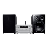
Related product manuals