Do you have a question about the Panasonic SA-PMX70EG and is the answer not in the manual?
General safety procedures, including leakage current checks and repair guidelines.
Guidelines to prevent damage to sensitive electronic components from static electricity.
Safety precautions when handling the laser diode component.
Guidelines for service work considering legal restrictions and lead-free solder.
Precautions for handling the traverse unit and optical pickup.
Technical information for understanding and servicing the unit.
Information and procedure for updating the unit's firmware.
Details on buttons and their functions on the main unit and remote.
Table of service modes, descriptions, and key operations.
Tables listing error codes for CD mechanism, power amp, and Bluetooth.
Detailed procedures for various doctor mode tests and operations.
Procedures to enter and cancel the sales demonstration lock function.
Troubleshooting steps for when the unit does not power on.
Troubleshooting steps for when there is no sound from the speakers.
List of potential failure causes categorized by unit function.
General notes, safety precautions, and an index for disassembly procedures.
Flow charts, screw types, and location diagrams for disassembly.
Step-by-step guides for removing major components like cabinets and PCBs.
Detailed procedure for replacing the traverse unit, including disassembly and assembly.
Procedure to check the Panel PCB.
Procedure to check the SMPS PCB.
Procedures to check the Main and CD Interface PCBs.
Diagram illustrating the servo and system control signal flow.
Diagram illustrating the audio signal flow and processing.
Diagrams showing the power supply circuitry (1/2 and 2/2).
Notes and symbols used in the schematic diagrams.
Schematic for the CD interface, tuner, and USB circuits.
Schematic diagram of the panel control circuit.
Schematic diagram for the IR sensor and headphone circuits.
Schematics for the Switch Mode Power Supply (SMPS) circuit (1/2 and 2/2).
Layouts of the CD interface, tuner, and USB printed circuit boards.
Layouts of the panel, IR sensor, and headphone printed circuit boards.
Layout of the Switch Mode Power Supply (SMPS) printed circuit board.
Table of standard voltage values for the main PCB.
Table of standard voltage values for the SMPS PCB.
Diagram showing the location of cabinet parts and their reference numbers.
Diagram illustrating the unit's packaging and included accessories.
List of mechanical parts with part numbers and descriptions.
List of electrical components with part numbers and descriptions.
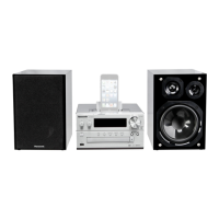
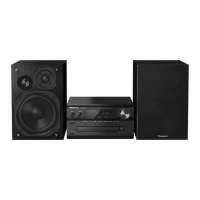
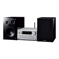
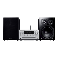
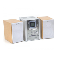
| Type | Micro Hi-Fi System |
|---|---|
| Output Power | 120 W |
| Speaker Configuration | 2.0 |
| USB | Yes |
| Bluetooth | Yes |
| Radio Tuner | Yes |
| FM | Yes |
| DAB+ | Yes |
| Weight | 3.4 kg |
| Number of Discs | 1 |
| Playable formats | CD, CD-R/RW, MP3 |
| Internet Radio | No |
| Ethernet | No |
| Wi-Fi | No |
| Headphone Jack | Yes |
| Frequency Response | 40 Hz - 20 kHz |
| Speaker Type | 2-way |
| Connectivity | USB, Bluetooth |
| Inputs | USB, AUX |
| Power Output | 60W per channel (6 Ohms, 1kHz, 10% THD) |




 Loading...