Do you have a question about the Panasonic SA-PM17E and is the answer not in the manual?
Details about the amplifier's power output and input sensitivity.
Technical details of the cassette deck, including heads, motor, and tape speed.
Specifications for the CD player, such as sampling frequency and beam source.
Explains the function of protection circuitry and conditions for its operation.
Details steps to enter the self-diagnostic mode.
How to view error codes and results from self-diagnosis.
Procedures to prevent damage from static electricity.
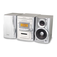
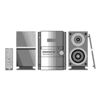
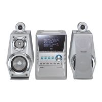
Description of the main unit's controls and indicators.
Step-by-step instructions for disassembling main PCBs.
Guides for replacing specific parts like cassette holder, pinch roller, motor, and optical pickup.
Steps for testing with a cassette tape inserted.
Detailed adjustments and tests for the cassette deck.
Critical procedure for adjusting cassette head azimuth.
Pinout and function for the main processor IC.
A detailed list of parts specific to the deck mechanism.
Extensive list of all resistors with specifications.
Extensive list of all capacitors with specifications.
First part of the overall schematic diagram.
Second part of the overall schematic diagram.
Third part of the overall schematic diagram.
Fourth part of the overall schematic diagram.
Eleventh part of the overall schematic diagram.
Thirteenth part of the overall schematic diagram.
PCB layout for the AC transformer.
PCB layout for the power supply.
PCB layout for the main and tuner sections.
PCB layout for the front panel.
| Brand | Panasonic |
|---|---|
| Model | SA-PM17E |
| Category | Stereo System |
| CD Player | Yes |
| Radio | Yes |
| Tuner Type | Digital |
| Preset stations quantity | 30 |
| USB Port | No |
| AUX Input | Yes |
| Speaker Configuration | 2.0 |
| Number of speakers | 2 |
| Total Harmonic Distortion | 10% |
| Playback disc formats | CD, CD-R, CD-RW |
| Audio formats supported | MP3 |
| Cassette deck | No |
| Equalizer | Yes |
| Equalizer bands quantity | 5 |
| Power consumption (standby) | 0.5 W |
| Type | Micro Hi-Fi System |
| Supported radio bands | FM |
| Power source | AC |
| Impedance | 6 Ω |