Block (Cassette Mechanism Unit)] under [9. Disassembly and Main
Component Replacement Procedures before Operation Checks].
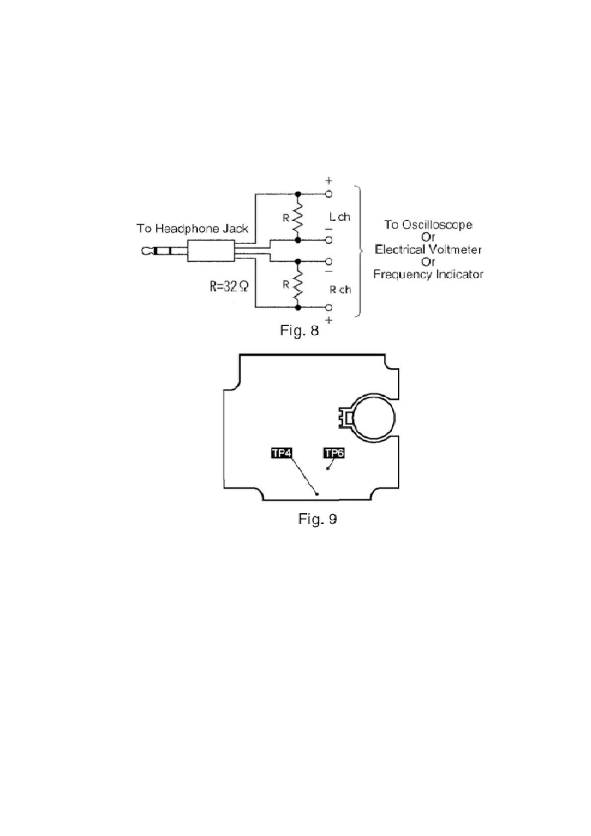
3. Connect the headphone jack output jig (cf. Fig. 8) to headphone
jack.
11.2.4. Head Azimuth Adjustment
1. Connect an oscilloscope. (Cf. Fig. 10)
2. Playback the azimuth adjustment portion (8kHz, -20dB) of the test
tape (QZZCFM). Adjust the azimuth adjusting screw so that the
output from Lch and Rch are set to maximum. (Cf. Fig. 11)
3. Adjust the azimuth by playing the test tape in reverse direction.
Check the level difference when the tape is played in forward and
reverse directions.
4. Playback the playback gain adjustment portion (315Hz, 0dB) of the
test tape (QZZCFM). Check that the level difference when the tape
59