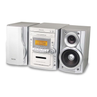
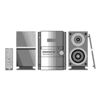
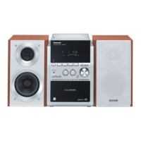
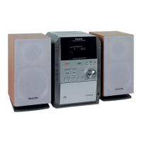
This document describes the Panasonic SA-PM19E / SA-PM19EB / SA-PM19EG CD Stereo System, available in Silver (S) and Black (K) types (Black for E only).
Function Description
The SA-PM19E series is a compact CD stereo system that integrates an amplifier, FM/AM tuner, cassette deck, and CD player. It supports various audio formats including CD, CD-R, CD-RW, and MP3. The system is designed for home audio use, offering playback from multiple sources and featuring a self-diagnostic display function for maintenance.
Important Technical Specifications
Amplifier Section
- RMS Power Output: 35 W per channel (6 Ω) at 1 kHz (Low channel) and 8 kHz (High channel) with 10% total harmonic distortion.
- Total Bi-Amp Power: 70 W per channel.
- Output Impedance (Headphone): 16 - 32 Ω.
FM Tuner Section
- Frequency Range: 87.50 - 108.00 MHz (50 kHz steps).
- Sensitivity: 1.5 µV (IHF), 1.5 µV (S/N 26 dB).
- Antenna Terminal(s): 75 Ω (unbalanced).
AM Tuner Section
- Frequency Range: 522 kHz - 1629 kHz (9 kHz steps), 520 kHz - 1630 kHz (10 kHz steps).
- Sensitivity (S/N 20 dB at 999 kHz): 560 µV/m.
Cassette Deck Section
- Track System: 4 track, 2 channel.
- Heads: Solid permalloy head (Record/playback), Double gap ferrite head (Erasure).
- Motor: DC servo motor.
- Recording System: AC bias 100 kHz.
- Erasing System: AC erase 100 kHz.
- Tape Speed: 4.8 cm/s.
- Overall Frequency Response (Normal Type I): 35 Hz - 14 kHz (+3 dB, -6 dB at Deck Out).
- S/N Ratio: 45 dB (A weighted).
- Wow and Flutter: 0.10% (WRMS).
- Fast Forward and Rewind Times: Approx. 120 seconds with C-60 cassette tape.
CD Section
- Disc Compatibility: CD, CD-R, CD-RW, MP3 (8 cm/12 cm).
- Sampling Frequency: 44.1 kHz.
- Decoding: 16 bit linear.
- Pickup: Semiconductor laser / 780 nm (Beam source/Wavelength).
- Number of Channels: Stereo.
- Frequency Response: 20 Hz - 20 kHz (+1dB, -2dB).
- Wow and Flutter: Below measurable limit.
- Digital Filter: 8 fs.
- D/A Converter: MASH (1 bit DAC).
MP3
- Bit Rate: 32kbps-320kbps.
- Sampling Frequency: 32kHz, 44.1kHz, 48kHz.
General
- Power Supply: AC 230 V, 50 Hz (E, EG) or AC 230 V - 240 V, 50 Hz (EB).
- Power Consumption: 130 W.
- Power Consumption in Standby Mode: 0.8W.
- Dimensions (W x H x D): 179 x 250 x 383 mm.
- Mass: 5.24 kg.
Usage Features
The system is designed for straightforward operation with a remote control transmitter included. It features a compact design suitable for various living spaces. The CD player supports multiple disc types, including MP3, offering versatility in music playback. The cassette deck provides traditional analog audio recording and playback capabilities.
Maintenance Features
The manual provides comprehensive instructions for repair and adjustment, emphasizing safety precautions.
Safety and Handling
- AC Mains Lead Caution: Specific instructions for handling the AC mains lead are provided.
- Disconnection and Discharge: Before any repair, AC power must be disconnected, and power supply capacitors (C506, C507, C508, C584 & C311) must be discharged through a 10 Ω, 5W resistor to ground. Short-circuiting directly is warned against to prevent damage to solid-state devices.
- Lead-free Solder (PbF): PbF PCBs are marked with "PbF". Lead-free solder has a higher melting point (50-70°F / 30-40°C higher) requiring a high-temperature soldering iron (700 ± 20°F / 370 ± 10°C). It tends to splash if heated too high (about 1100°F/600°C). Complete removal of old solder and proper heating with PbF solder are crucial.
- Laser Diode Precaution: The product uses an invisible laser diode (780 nm, 100 µW/VDE output). Users are warned not to disassemble the optical pickup unit, adjust the variable resistor on the pickup, or look at the focus lens with optical instruments or for prolonged periods.
- Electrostatic Breakdown Prevention: The laser diode in the optical pickup is extremely sensitive to static electricity. Technicians must use an anti-static wrist strap and ground the work table with a conductive sheet to prevent damage. Clothes should not touch the optical pickup.
Disassembly and Assembly
- Flow Chart: A detailed disassembly flow chart is provided for internal inspection and servicing, with instructions to reverse the steps for assembly.
- Specific Procedures: Step-by-step procedures are outlined for disassembling various components, including side panels, top cabinet, deck P.C.B., tape eject P.C.B., front panel, panel P.C.B., headphone P.C.B., switch P.C.B., tact switch P.C.B., rear panel, main P.C.B., transformer P.C.B., speaker terminal P.C.B., power P.C.B., and CR16 mechanism.
- Component Replacement: Procedures for replacing the power amplifier IC, cassette holder, pinch roller, head block, motor, capstan belts, winding belt, parts on the mechanism PCB, CD traverse deck, optical pickup unit, traverse gears, and CD loading mechanism are detailed.
- CR16 Mechanism Disassembly: Specific instructions for removing the CD loading mechanism and using a "gear for servicing" to check disc tray and traverse unit operations are included.
- Grease and Oil Application: Floil grease (VFK1298) is specified for the tray, tray (L), and tray (R), while Hanarl oil (VFK1700) is for other greased parts during CR16 mechanism assembly.
Self-Diagnostic Display Function
- Purpose: The unit includes a self-diagnostic display function to assist with servicing and maintenance.
- Preparations: Requires a Cr02-positioned blank cassette tape with an erase prevention niche, a normal-positioned music tape with erase prevention niches (both halfway forwarded), and the remote controller.
- Setting Mode: Enter self-diagnostic mode by switching the SELECTOR to TAPE (no cassettes loaded), then pressing [STOP / -DEMO] for 2 seconds, followed by [ / FF / ] for another 2 seconds.
- Restoring Normal Display: Pressing the "POWER" button turns off and on the power to restore normal display from most error codes, except F76 which requires error recovery.
- Clearing Memory: Instructions for clearing self-diagnostic memory for the CD section (F15, F17, F22, F26, F27, F28, F29) are provided.
- Error Detection Codes: A table lists error codes, abnormal items, and possible causes for both CD Block and Cassette Mechanism Block, aiding in troubleshooting.
- Doctor Mode: A special "Doctor Mode" can be entered using a specific remote control key sequence (input 4 then 7 while pressing STOP on the main set).
- Cold Start Setting: Instructions for cold start setting are included, noting that unplugging from AC outlet after setting will initiate a cold start.
Operation Check of Individual Parts (Cassette Mechanism Unit)
- Cassette Tape Check: Procedures for checking operation with a cassette tape, including using a rubber band for the EJECT lever, supplying DC5V to the motor, inserting a tape, and supplying DC9V to the plunger for FWD PLAY, FWD FF, STOP, REV PLAY, REV REW, and STOP (FF mode).
- Without Cassette Tape Check: Procedures for checking operation without a cassette tape, involving the EJECT lever, motor power, and lifting the plunger/rib with a screwdriver.
Measurement and Adjustments
- Tuner/CD Sections: No adjustment required.
- Cassette Deck Section:
- Requirements: Test tape (QZZCFM, QZZCWAT), normal blank cassette tape (QZZCRA), frequency indicator, oscilloscope, electrical voltmeter, and headphone jack output jig.
- Setting: VOLUME: MAX.
- Preparations: Disassemble the mechanism unit and connect the headphone jack output jig.
- Tape Speed Adjustment: Normal speed adjustment (3,000±90Hz) during forward playback, adjusted via the motor screw using a frequency indicator.
- Bias Voltage Check: Check output level (14 ± 4mV) using an electrical voltmeter during recording pause mode with a blank cassette tape.
- Bias Frequency Check: Check output frequency (98 ±8 kHz) using a digital frequency counter during recording mode with a blank cassette tape.
Schematic Diagrams and Parts Lists
- Block Diagrams: Provided for CD Servo Block and Main Block.
- Schematic Diagrams: Detailed diagrams for CD Servo Circuit, Main Circuit, Panel Circuit, Tact Switch Circuit, Switch Circuit, Headphone Circuit, Cassette Deck Circuit, Deck Mechanism Circuit, Tape Eject Circuit, Power Circuit, Transformer Circuit, Speaker Terminal Circuit, and CD Loading Circuit.
- Terminal Functions: Lists functions for IC701 (AN22004A-NF) IC HEAD AMP, IC702 (MN6627934CH) IC LSI, IC703 (BA5948FPE2) IC 4CH DRIVE, and IC302 (C2CBJF000016) MICRO PROCESSOR.
- Parts Location and Replacement Parts List: Detailed lists for Deck Mechanism, CD Loading Mechanism, Cabinet, and Electrical Parts, with important safety notices regarding component replacement and retention times.