17. Printed Circuit Board
17.1. CD Servo P.C.B. (SIDE A and SIDE B)
17.2. Main P.C.B.
17.3. Panel P.C.B. and Tact Switch P.C.B.
17.4. Switch P.C.B., Headphone P.C.B. and Speaker Terminal P.C.B.
17.5. Deck P.C.B. and Tape Eject P.C.B.
17.6. Deck Mechanism P.C.B. and CD Loading P.C.B.
17.7. Power P.C.B.
17.8. Transformer P.C.B.
18. Wiring Connection Diagram
19. Illustration of IC’s, Transistors and Diodes
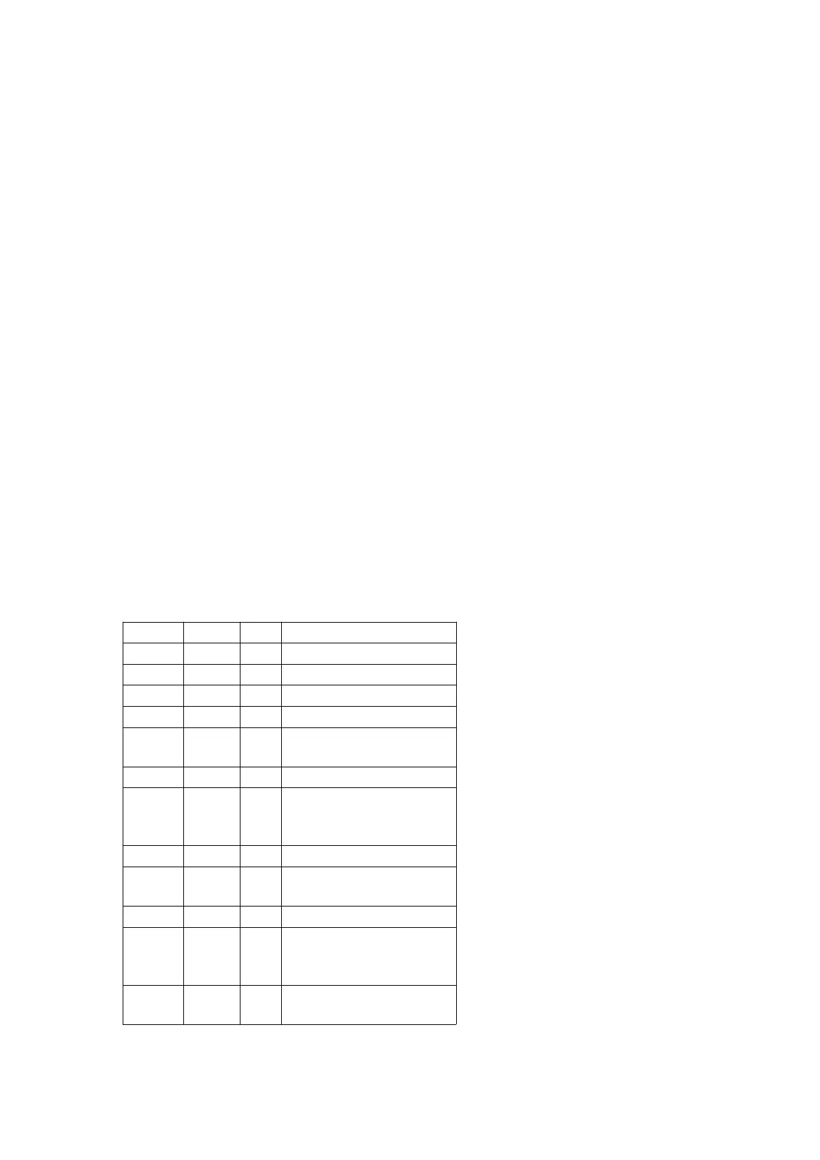
20. Terminal Function of IC's
20.1. IC701 (AN22004A-NF) IC HEAD AMP
Pin No. Mark I/O Function
1 LPD I APC Amp input terminal
2 LD O APC Amp. output terminal
3 VCC I Power source terminal
4 EQSW - Equalizer switch terminal
5 RFOUT O RF summing Amp output
terminal
6 RFIN I AGC input terminal
7 AGC - AGC loop filter
connecting capacitor
terminal
8 AGC O AGC output terminal
9 HPF-
AMP
- HPF Amp connecting
capacitor terminal
10 3TOUT O 3TOUT output terminal
11
HPFDET
- Detection system’s HPF
connecting capacitor
terminal
12
OFTCNT
- PFTR detection level
adjustment terminal
87