36
10 Service Position
Note: For description of the disassembly procedures, see the Section 8
10.1. Checking of SMPS P.C.B.
Step 1 : Remove Top Cabinet Assembly.
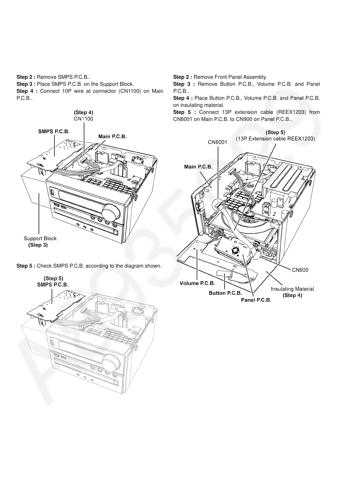
Step 2 : Remove SMPS P.C.B..
Step 3 : Place SMPS P.C.B. on the Support Block.
Step 4 : Connect 10P wire at connector (CN1100) on Main
P.C .B . .
Step 5 : Check SMPS P.C.B. according to the diagram shown.
10.2. Checking of Panel P.C.B.
Step 1 : Remove Top Cabinet Assembly.
Step 2 : Remove Front Panel Assembly.
Step 3 : Remove Button P.C.B., Volume P.C.B. and Panel
P.C.B..
Step 4 : Place Button P.C.B., Volume P.C.B. and Panel P.C.B.
on insulating material.
Step 5 : Connect 13P extension cable (REEX1203) from
CN8001 on Main P.C.B. to CN900 on Panel P.C.B..