D/A converter MASH (1 bit DAC)
n General
Power supply
For continental Europe AC 230 V, 50 Hz
For United Kingdom, Australia and
N.Z.
AC 230-240 V, 50 Hz
Power consumption 130 W
Dimensions (W x H x D) 179 x 250 x 383 mm
Mass 5.6 kg
Power consumption in standby
mode
Approx 0.9 W
1 Caution for AC Mains Lead
4
2 Before Repair and Adjustment
5
3 Protection Circuitry
5
4 Handling the Lead-free Solder
6
4.1. About lead free solder (PbF)
6
5 Precaution of Laser Diode
7
6 Handling Precautions For Traverse Deck
9
7 Accessories
10
8 Operation Procedures
11
9 Information on MP3 & WMA
12
10 About HighMAT
14
10.1. What is HighMAT?
14
10.2. Why use HighMAT?
14
10.3. The advantages of using HighMAT
14
10.4. Outline of the HighMAT standard
15
11 Assembling and Disassembling
18
11.1. Disassembly flow chart
18
11.2. Disassembly of Side Panel L & R
19
11.3. Disassembly of Top Cabinet
19
11.4. Disassembly of Deck Mechanism P.C.B and Tape Eject
P.C.B
19
11.5. Disassembly of Front Panel
20
11.6. Disassembly of Panel P.C.B, Headphone P.C.B, Switch
P.C.B and Tact switch P.C.B
20
11.7. Disassembly of Rear Panel
21
11.8. Disassembly of Main P.C.B
22
11.9. Disassembly of Transformer P.C.B
22
11.10. Disassemb ly of Speaker Terminal P.C.B
23
11.11. Disassemb ly of Power P.C.B
23
11.12. Replaceme nt of the Power Amplifier IC
24
11.13. Procedure for Replacing Cassette Holder
24
11.14. Procedure for Replacing Pinch Roller and Head Block
(Cassette Mechanism Unit)
25
Notes :
1. Specifications are subject to change without notices. Mass and
dimensions are approximate.
2. Total harmonic distortion is measured by the digital spectrum
analyzer.
3.The labels “HIGH (HF)” and “Low (LF)” on the rear of the speakers
refer to High frequency and Low frequency.
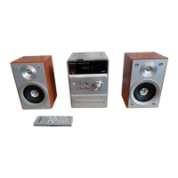
n System : SC-PM29E-S
Music center: SA-PM9E-S
Speaker: SB-PM29P-K
n System : SC-PM29EB-S
Music center: SA-PM29EB-S
Speaker: SB-PM29P-K
n System : SC-PM29EG-S
Music center: SA-PM29EG-S
Speaker: SB-PM29EG-K
11.15. Procedure for Replacing Motor, Capstan Belt A, Capstan
Belt B, and Winding Belt (Cassette Mechanism Unit)
26
11.16. Procedure for Replacing Parts on Mechanism PCB
27
11.17. Disassemb ly of CR16 Mechanism
28
11.18. Replaceme nt of optical pickup unit (CD mechanism)
29
11.19. Replaceme nt of a traverse gear A and a traverse gear B
31
11.20. Procedure for removing CD loading mechanism
32
11.21. CR16 mechanism disassembly procedure
32
11.22. CR16 MECHANIS M ASSEMBLY PROCEDU RE
38
11.23. Disassemb ly of traverse mechanism
51
11.24. Handling of cassette tape jam
52
12 Service Positions
53
12.1. Checking procedure
53
12.2. Checking the major P.C.B
53
13 Self-Diagnostic Display Function
54
13.1. Preparations
54
13.2. Setting of the Self-Diagnostic Mode
54
13.3. Restoring Normal Display
54
13.4. Clearing Self-Diagnostic Memory
54
13.5. Displaying Self-Diagnostic Results
54
14 Procedure for Checking Operation of Individual Parts for
Cassette Mechanism Unit
57
14.1. Operation Check with Cassette Tape
57
14.2. Operation Check without Cassette Tape
57
15 Measurement And Adjustments
59
15.1. Cassette Deck Section
59
16 Block Diagram
61
16.1. CD Servo Block
61
16.2. Main Block
63
17 Notes of Schematic Diagram
69
18 Schematic Diagram
70
18.1. CD Servo Circuit
70
CONTENTS
Page Page
2
SA-PM29E / SA-PM29EB / SA-PM29EG
 Loading...