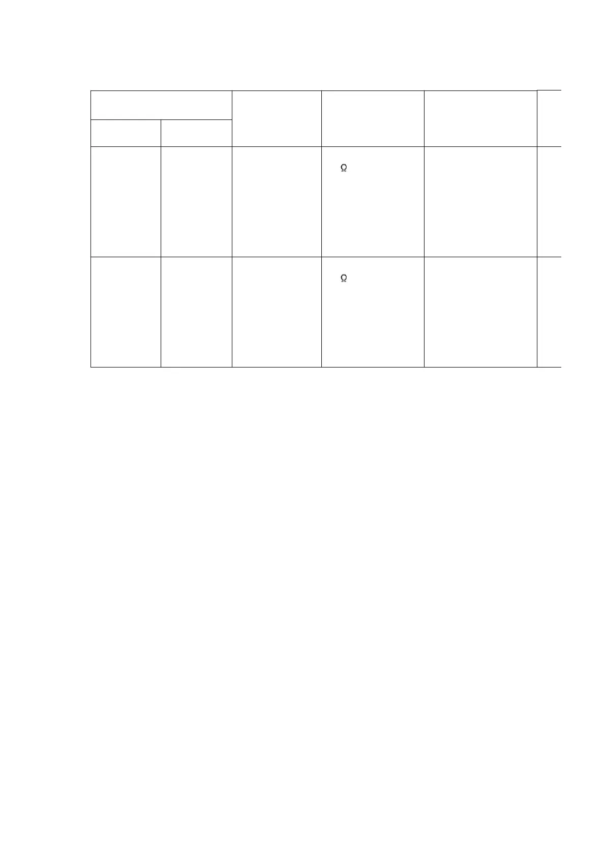
SIGNAL GENERATOR OR
SWEEP GENERATOR
RADIO DIAL
SETTING
INDICATOR
(ELECTRONIC
VOLTMETER
OSCILLOSCOPE)
ADJUSTMENT(Shown
in Fig.9)
CONNECTIONS
FREQUENCY
Fashion a
loop of
several turns
of wire and
radiate
signal into
loop of
receiver.
522 kHz Tuning capacitor
fully closed.
Headphone Jack
(32 ) Fabricate the
plug as shown in
Fig. 2 and then
connect the lead
wires of the plug to
the measuring
instrument.
Z1 (AM OSC Coil)
Fashion a
loop of
several turns
of wire and
radiate
signal into
loop of
receiver.
603 kHz Tuning capacitor
fully open.
Headphone Jack
(32 ) Fabricate the
plug as shown in
Fig. 2 and then
connect the lead
wires of the plug to
the measuring
instrument.
Z1 (AM ANT Coil)
12.2. Cassette Deck Section
12.2.1. Requirements
- Test tape (QZZCFM) (QZZCWAT)
- Normal blank cassette tape (QZZCRA)
- Digital frequency counter
- Oscilloscope
- Electrical voltmeter
- Headphone jack output jig (Cf. Fig. 8)
12.2.2. Setting of Unit
- VOLUME: MAX
12.2.3. Preparations
1. Apply [8.1 Checking for Main & Transformer P.C.B., Deck P.C.B.,
Headphone P.C.B. and Tape Eject P.C.B.] under [8. Operation
Check and Main Component Replacement Procedures].
2. Remove 4 screws from the mechanism unit to disassemble. (Refer
to [8.4 Procedure for Replacing Cassette Holder (Step 1) under [8.
Operation Check and Main Component Replacement Procedures].
3. Connect the headphone jack output jig (Cf. Fig. 8) to headphone
jack.
38