EasyManua.ls Logo

Panasonic SA-XH170EB User Manual

Panasonic SA-XH170EB
145 pages
To Next Page IconTo Next Page
Page #1 background imageLoading...
Page #1 background image
© Panasonic Corporation 2012. All rights reserved.
Unauthorized copying and distribution is a violation
of law.
PSG1202014CE
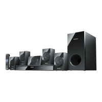
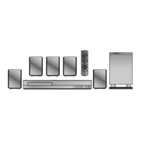
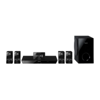
DVD Home Theater Sound System
Model No. SA-XH170EB
SA-XH170EG
SA-XH175EP
Product Color: (K)...Black Type
TABLE OF CONTENTS
PAGE PAGE
1 Safety Precautions----------------------------------------------- 3
1.1. General Guidelines---------------------------------------- 3
1.2. Before Repair and Adjustment ------------------------- 4
1.3. Protection Circuitry---------------------------------------- 4
1.4. Caution For AC Cord (For EB only)------------------- 5
1.5. Caution For Fuse Replacement------------------------ 6
1.6. Safety Part Information----------------------------------- 7
2 Warning-------------------------------------------------------------- 8
2.1. Prevention of Electrostatic Discharge (ESD)
to Electrostatic Sensitive (ES) Devices -------------- 8
2.2. Precaution of Laser Diode------------------------------- 9
2.3. Service caution based on Legal restrictions-------10
2.4. Handling Precautions for Traverse Unit-------------11
3 Service Navigation----------------------------------------------13
3.1. Service Information-------------------------------------- 13
4 Specifications---------------------------------------------------- 14
4.1. Others (Licences) ---------------------------------------- 15
5 General/Introduction------------------------------------------- 16
5.1. Power-Saving Features -------------------------------- 16
5.2. Linked Operations with the TV (VIERA Link™
“HDAVI Control™”) ------------------------------------- 17
5.3. Disc Information ------------------------------------------ 18
5.4. DivX Information------------------------------------------ 19
6 Location of Controls and Components------------------ 20
6.1. Remote Control Key Button Operations------------ 20
6.2. Main Unit Key Button Operations-------------------- 21
7 Installation Instructions -------------------------------------- 22
7.1. Speaker Connections ---------------------------------- 22
Note: Please refer to the original service manual for:
O DVD Mechanism Unit (BRS11D), Order No. PSG1201015AE
O Speaker system SB-XH170PC-K (For SA-XH170EB/EG-K), Order No. PSG1201002CE
O Speaker system SB-XH175EP-K (For SA-XH175EP-K), Order No. PSG1202026CE

Table of Contents

Questions and Answers:

Panasonic SA-XH170EB Specifications

General IconGeneral
TypeHome Theater System
Audio Channels5.1
Playable MediaDVD, CD, USB
Audio FormatsDolby Digital, DTS
RadioFM
BluetoothYes
HDMI Outputs1
USB Port1
Optical Input1
Coaxial Input1
ConnectivityBluetooth, USB

Summary

1 Safety Precautions

1.1. General Guidelines

General safety guidelines for servicing the unit.

1.2. Before Repair and Adjustment

Precautions to take before starting any repair or adjustment.

1.3. Protection Circuitry

Explains the unit's protection circuitry and how it functions.

1.4. Caution For AC Cord (For EB only)

Specific caution regarding the AC power cord for EB models.

1.6. Safety Part Information

Lists safety-critical components requiring specific replacement parts.

2 Warning

2.1. Prevention of Electrostatic Discharge (ESD)

Measures to prevent damage to sensitive components from static electricity.

2.2. Precaution of Laser Diode

Safety precautions related to the product's laser diode.

2.4. Handling Precautions for Traverse Unit

Specific handling instructions for the traverse unit to prevent damage.

3 Service Navigation

3.1. Service Information

Introduction to the service manual's scope and ordering procedures.

4 Specifications

4.1. Others (Licences)

Details on various licenses and third-party software acknowledgments.

Disc Section

Lists compatible disc types and file format support.

DivX Information

Information regarding DivX video playback and registration.

5 General/Introduction

5.1. Power-Saving Features

Information on the unit's automatic power-saving functions.

5.2. Linked Operations with the TV (VIERA Link™ “HDAVI Control™”)

Explains how the unit interacts with TVs using VIERA Link technology.

6 Location of Controls and Components

6.1. Remote Control Key Button Operations

Explains the functions of each button on the remote control.

6.2. Main Unit Key Button Operations

Describes the operations for buttons located on the main unit.

7 Installation Instructions

7.1. Speaker Connections

Guidance on how to connect the speaker systems to the unit.

7.3. Connection with an ARC compatible TV

Instructions for connecting the unit to a TV using ARC via HDMI.

8 Operating Instructions

8.1. Removing of disc during abnormality

Procedures for ejecting a disc when the unit is not functioning normally.

8.2. Playing From an USB Device

Steps for playing media files from a connected USB device.

9 Service Mode

9.1. Cold-Start

Procedure to initialize the unit to its shipping mode settings.

9.2. Panel Code Setting Operation

Instructions for setting or checking the unit's panel code.

9.3. Self Diagnostic

Explains how to activate and interpret self-diagnostic modes for troubleshooting.

9.4. Error Code

Lists and explains various error codes displayed by the unit.

10 Troubleshooting Guide

10.1. Troubleshooting Guide for F61 and/or F76

Troubleshooting steps for specific power supply and amplifier errors.

10.2. DVD/CD Laser Diode current measurement

Procedures for measuring and calculating laser diode currents.

10.3. Basic Troubleshooting Guide for Traverse Unit (Main P.C.B.)

Common issues and checks for the disc traverse unit.

10.4. Basic Troubleshooting Guide for HDMI AV output

Guides for resolving problems with HDMI audio and video output.

11 Service Fixture & Tools

Service Fixture & Tools

Lists necessary service tools and fixtures for disassembly.

12 Disassembly and Assembly Instructions

12.1. Screw Type

Identifies different types of screws used in the unit.

12.2. Disassembly Flow Chart

Visual representation of the disassembly process sequence.

12.3. Main Components and P.C.B. Locations

Illustrates the location of major components and PCBs within the unit.

12.4. Disassembly of Top Cabinet

Step-by-step instructions for removing the top cabinet cover.

12.5. Replacement of Tray Ornament

Replacement of Tray Ornament

Procedure for replacing the tray ornament component.

12.6. Disassembly of Front Panel Block Assembly

Disassembly of Front Panel Block Assembly

Steps for removing the front panel assembly.

Disassembly of Operation Button P.C.B.

Instructions for disassembling the operation button PCB.

Disassembly of Power Button P.C.B.

Steps for removing the power button PCB.

Disassembly of Panel P.C.B.

Procedure for disassembling the main panel PCB.

12.10. Disassembly of Rear Panel

Disassembly of Rear Panel

Instructions for removing the rear panel of the unit.

Disassembly of Fan Unit

Steps for removing the unit's fan.

Disassembly of Main P.C.B.

Detailed steps for removing the main printed circuit board.

Disassembly of D-Amp P.C.B.

Instructions for disassembling the D-Amp PCB.

12.14. Replacement of Digital Amplifier IC (IC5100/IC5200/IC5300)

Replacement of Digital Amplifier IC

Guide for replacing the digital amplifier integrated circuits.

Disassembly of AC Inlet P.C.B.

Steps to disassemble the AC inlet PCB.

Disassembly of SMPS P.C.B.

Steps to disassemble the Switched-Mode Power Supply (SMPS) PCB.

12.17. Replacement of Switching Regulator IC (IC5701)

Disassembly of Switching Regulator IC (IC5701)

Procedure for removing the switching regulator IC.

Replacement of Diode (D5702)

Steps for removing the D5702 diode.

Replacement of Diode (D5802)

Procedure for removing the D5802 diode.

Replacement of Diode (D5803)

Steps for removing the D5803 diode.

12.21. Disassembly of Scart P.C.B.

Disassembly of Scart P.C.B.

Instructions for disassembling the Scart PCB.

Disassembly of DVD Mechanism Unit (BRS11D)

Instructions for disassembling the DVD mechanism unit.

Replacement of Traverse unit

Steps for disassembling and replacing the traverse unit.

13 Service Position

13.1. Checking & Repairing of Panel P.C.B.

Guidance on checking and repairing the panel PCB.

13.2. Checking & Repairing Main P.C.B.

Steps for checking and repairing the main PCB.

13.3. Checking and Repairing D-Amp P.C.B.

Instructions for checking and repairing the D-Amp PCB.

13.4. Checking & Repairing of SMPS P.C.B.

Procedures for checking and repairing the SMPS PCB.

14 Overall Simplified Block Diagram

Overall Simplified Block Diagram

A high-level overview of the unit's functional blocks.

15 Block Diagram

15.1. Backend

Detailed block diagram of the unit's backend processing.

15.2. IC Terminal Chart

Lists terminal pinouts for key integrated circuits.

15.3. System Control

Illustrates the system control signal flow and components.

15.4. Audio & Video

Block diagram detailing the audio and video signal paths.

16 Wiring Connection Diagram

Wiring Connection Diagram

Shows how various PCBs and components are interconnected via wiring.

17 Schematic Diagram

17.1. Schematic Diagram Notes

Explains symbols and conventions used in the schematic diagrams.

17.2. Main(HDMI/Micon) Circuit

Detailed schematic for the main processing and HDMI interface circuits.

17.3. Panel Circuit

Schematic detailing the front panel control circuitry.

17.4. Operation Button, Power Button & AC Inlet Circuit

Schematics for the operation button, power button, and AC inlet circuits.

18 Printed Circuit Board

18.1. Main P.C.B.

Layout diagram of the main printed circuit board.

18.2. Panel, Operation Button & Power Button P.C.B.

Layouts for the panel, operation, and power button PCBs.

18.3. D-Amp P.C.B.

Layout diagram of the D-Amp printed circuit board.

18.4. SMPS, AC Inlet & Scart P.C.B.

Layouts for the SMPS, AC inlet, and Scart PCBs.

19 Appendix Information of Schematic Diagram

19.1. Voltage & Waveform Chart

Provides voltage readings and waveform examples for troubleshooting.

19.2. Illustration of ICs, Transistor and Diode

Visual identification guide for common electronic components.

19.3. Terminal Function of ICs

Detailed pin functions for key integrated circuits.

20 Exploded View and Replacement Parts List

20.1. Exploded View and Mechanical Replacement Parts List

Visual breakdown of mechanical parts and their locations.

20.1.2. Packaging (For SC-XH170EB/EG-K)

Illustrates the packaging of the SC-XH170EB/EG model.

20.1.3. Packaging (For SC-XH175EP-K)

Illustrates the packaging of the SC-XH175EP model.

20.1.4. Mechanical Replacement Part List

Lists all mechanical parts for replacement.

20.2. Electrical Replacement Parts List

Electrical Replacement Parts List

Comprehensive list of electrical components for replacement.

Related product manuals