EasyManua.ls Logo

Panasonic SA-XH20PH User Manual

Panasonic SA-XH20PH
129 pages
To Next Page IconTo Next Page
Page #1 background imageLoading...
Page #1 background image
© Panasonic Corporation 2012. All rights reserved.
Unauthorized copying and distribution is a violation
of law.
PSG1204015CE
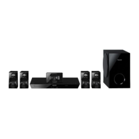
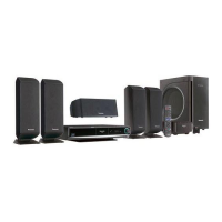
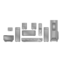
DVD Home Theater Sound System
Model No. SA-XH20PH
Product Color: (K)...Black Type
TABLE OF CONTENTS
PAGE PAGE
1 Safety Precautions----------------------------------------------- 3
1.1. General Guidelines---------------------------------------- 3
1.2. Before Repair and Adjustment ------------------------- 4
1.3. Protection Circuitry---------------------------------------- 4
1.4. Caution For Fuse Replacement------------------------ 4
1.5. Safety Part Information----------------------------------- 5
2 Warning-------------------------------------------------------------- 6
2.1. Prevention of Electrostatic Discharge (ESD)
to Electrostatic Sensitive (ES) Devices -------------- 6
2.2. Precaution of Laser Diode------------------------------- 7
2.3. Service caution based on Legal restrictions-------- 8
2.4. Handling Precautions for Traverse Unit-------------- 9
3 Service Navigation----------------------------------------------11
3.1. Service Information --------------------------------------11
4 Specifications ----------------------------------------------------12
4.1. Others (Licences)-----------------------------------------13
5 General/Introduction------------------------------------------- 14
5.1. Power-Saving Features -------------------------------- 14
5.2. Disc Information ------------------------------------------ 15
5.3. DivX Information------------------------------------------ 17
6 Location of Controls and Components------------------ 18
6.1. Remote Control Key Button Operations------------ 18
6.2. Main Unit Key Button Operations-------------------- 19
7 Installation Instructions -------------------------------------- 20
7.1. Speaker Connections ----------------------------------- 20
7.2. Radio Antenna Connection---------------------------- 21
8 Operating Instructions ---------------------------------------- 22
8.1. Removing of disc during abnormality --------------- 22
9 Service Mode----------------------------------------------------- 24
9.1. Cold-Start -------------------------------------------------- 24
9.2. Panel Code Setting Operation------------------------ 24
9.3. Self Diagnostic-------------------------------------------- 27
Note: Please refer to the original service manual for:
O DVD Mechanism Unit (BRS1D), Order No. PSG1012001CE
O Speaker system SB-XH70GS-K, Order No. PSG1202009CE

Table of Contents

Questions and Answers:

Panasonic SA-XH20PH Specifications

General IconGeneral
TypeHome Theater System
Number of Channels5.1
DVD PlayerYes
Total Output Power1000 W
Audio formatsDolby Digital, DTS
Progressive ScanYes
Component Video OutputYes
Composite Video OutputYes
Radio TunerFM/AM
Speaker Configuration5.1
Playback FormatsDVD, CD, MP3
InputsHDMI
OutputsHDMI, Composite

Summary

Safety Precautions

General Guidelines

General guidelines for safe servicing practices, including leakage checks.

Before Repair and Adjustment

Precautions to take before performing repairs or adjustments.

Protection Circuitry

Information about the unit's protection circuitry and its function.

Fuse Replacement Cautions

Important cautions to observe when replacing fuses.

Safety Part Information

Identifies critical parts essential for safety requiring manufacturer's parts.

Warning

ESD Prevention

Techniques to prevent damage to sensitive electronic components from static discharge.

Laser Diode Precautions

Safety precautions when working with or near the laser diode.

Legal Restrictions Cautions

Cautions related to legal requirements, like lead-free solder usage.

Traverse Unit Handling

Specific handling precautions for the traverse unit to prevent damage.

Service Navigation

Service Information

Information for service personnel on understanding and servicing the model.

Specifications

Licences

Information on various licenses and trademarks used in the product.

Product Introduction

Power-Saving Features

Explanation of the unit's power-saving functionalities.

Disc Information

Details on compatible disc types and media formats.

DivX Information

Information regarding DivX video playback and registration.

Controls and Components

Remote Control Operation

Detailed explanation of each button's function on the remote control.

Main Unit Controls

Description of functions for buttons located on the main unit.

Installation Instructions

Speaker Connections

Instructions on how to properly connect the speakers to the main unit.

Antenna Connection

Guidance on connecting the FM antenna for optimal reception.

Operating Instructions

Disc Ejection

Procedures for ejecting a disc when the unit is not functioning normally.

Service Mode

Cold-Start

Procedure to initialize the unit to its shipping mode.

Panel Code Setting

Operation for setting the panel code for regional compatibility.

Self Diagnostic

Performing system self-diagnostics for troubleshooting.

Error Code

Table of error codes and their meanings for troubleshooting.

Sales Demonstration Lock

Function to prevent disc ejection during sales demonstrations.

Firmware Update

Steps and process for updating the unit's firmware.

Troubleshooting Guide

F61/F76 Errors

Specific troubleshooting steps for error codes F61 and F76.

Laser Diode Measurement

Procedures for measuring laser diode current for DVD and CD playback.

Traverse Unit Troubleshooting

Troubleshooting steps for issues related to the traverse unit and backend PCB.

HDMI AV Output Troubleshooting

Troubleshooting steps for problems with HDMI audio and video output.

Service Tools

Disassembly Instructions

Screw Types

Identification of screw types used in the unit for disassembly.

Disassembly Flow Chart

Visual flow chart illustrating the disassembly process sequence.

Component Locations

Diagram showing the locations of major components and PCBs.

Top Cabinet Disassembly

Detailed steps for removing the top cabinet.

Tray Ornament Replacement

Procedure for replacing the tray ornament.

Front Panel Disassembly

Steps for disassembling the front panel assembly.

Panel PCB Disassembly

Procedure for removing the panel printed circuit board.

Power Button PCB Disassembly

Steps for disassembling the power button PCB.

Rear Panel Disassembly

Procedure for removing the rear panel.

SMPS PCB Disassembly

Steps for removing the Switched-Mode Power Supply (SMPS) PCB.

Current Limiting Switch Replacement

Procedure for replacing the current limiting switch.

Diode Replacement

Procedure for replacing a specific diode.

Main PCB Disassembly

Steps for removing the main printed circuit board.

Digital Amplifier IC Replacement

Procedure for replacing digital amplifier ICs.

Backend PCB Disassembly

Steps for removing the backend printed circuit board.

Component Video PCB Disassembly

Procedure for removing the component video PCB.

DVD Mechanism Disassembly

Steps for removing the DVD mechanism unit.

Traverse Unit Replacement

Procedure for replacing the traverse unit.

Service Position

Panel PCB Check/Repair

Steps for checking and repairing the panel PCB.

SMPS PCB Check/Repair

Steps for checking and repairing the SMPS PCB.

Main PCB Check/Repair

Steps for checking and repairing the main PCB.

Backend PCB Check/Repair

Steps for checking and repairing the backend PCB.

Simplified Block Diagram

Block Diagrams

Backend Block Diagram

Block diagram of the backend circuitry.

IC Terminal Chart

Pin assignments and terminal functions for key ICs.

System Control Diagram

Block diagram showing the system control functions.

Audio and Video Diagram

Block diagram illustrating audio and video signal paths.

Power Supply Diagram

Block diagram of the power supply unit.

Wiring Connection Diagram

Schematic Diagrams

Schematic Notes

Notes and symbols used in the schematic diagrams.

Backend Circuit Schematic

Schematic diagram of the backend circuit.

Main Circuit Schematic

Schematic diagram of the main circuit.

Panel/Power Button Schematic

Schematic diagram for the panel and power button circuits.

SMPS Circuit Schematic

Schematic diagram of the Switched-Mode Power Supply (SMPS) circuit.

Component Video Schematic

Schematic diagram for the component video output circuit.

PCB Layouts

Backend PCB Layout

Layout diagram for the backend PCB.

Main PCB Layout

Layout diagram for the main PCB.

Panel/Power/Video PCB Layouts

Layout diagrams for panel, power button, and video PCBs.

SMPS PCB Layout

Layout diagram for the SMPS PCB.

Appendix Information

Voltage & Waveform Charts

Table of voltage values and waveforms for key test points across PCBs.

Component Illustrations

Visual illustrations of common electronic components like ICs and diodes.

IC Terminal Functions

Detailed pin descriptions for integrated circuits.

FL Display Driver IC Functions

Terminal functions for the FL display driver IC.

Parts List & Exploded Views

Mechanical Parts

Exploded views and lists of mechanical parts for replacement.

Electrical Parts List

List of electrical components available as replacement parts.

Related product manuals