Do you have a question about the Panasonic SA-HT650P and is the answer not in the manual?
Fundamental safety principles applicable to all servicing operations.
Procedures for performing cold and hot leakage current tests for electrical safety.
Definition and introduction to the HighMAT format standard.
Reasons and benefits for adopting the HighMAT standard for digital content.
Key benefits and improvements offered by the HighMAT standard for user experience.
Overview of the HighMAT standard, covering recording media and data formats.
Details on the data formats supported by HighMAT players at different levels.
Specific constraints and limitations regarding WMA, MP3, and JPEG file formats in HighMAT.
Explanation of the structure of a HighMAT disc, including menus and playlists.
Methods for grounding equipment and personnel to prevent ESD damage to the optical pickup.
Methods for grounding the human body using anti-static wrist straps to prevent ESD.
Precautions for handling the optical pickup during transportation and installation.
Specific precautions for handling the traverse unit, focusing on its precision and cable connections.
Procedure for checking the DVD B/E Module and Power P.C.B. during disassembly.
Procedure for checking the Panel P.C.B. and Switch P.C.B. during disassembly.
Procedure for checking various DVD modules (1, CD Loading, ASP, DSP, Input) P.C.B.s.
Procedure for checking the DVD REG P.C.B. during disassembly.
Procedure for checking the Main P.C.B. during disassembly.
Step-by-step guide for replacing the Power IC component on the P.C.B.
Detailed procedure for replacing the DVD traverse unit, including disc tray and top plate removal.
Procedure for removing and replacing the disc tray mechanism.
Steps for disassembling and reassembling the mechanism base drive unit.
Procedure for replacing the motor assembly, including belt installation and unit checks.
Guide for performing self-diagnosis and effective tilt adjustment for the optical pickup.
Specific safety warnings for handling the optical pickup and its peripherals during replacement.
Details on error codes automatically displayed by the unit, including F61.
Explanation of error codes, their states, conditions, causes, and troubleshooting steps.
Procedures for activating, displaying, re-displaying, and deleting memorized error codes.
Steps for configuring the tray lock functions, such as disc lock and operation lock modes.
List of tools, test discs, and equipment required for unit adjustment and checking.
Detailed procedure for adjusting the optical pickup tilt for optimal performance.
Step-by-step guide for performing the optical pickup tilt adjustment using test discs.
Helpful tips and sequence recommendations for performing optical adjustment effectively.
Procedure for verifying the adjustment quality by checking for picture deterioration or sound skipping.
Steps to secure adjustment screws after completing the optical adjustment process.
Pinout and function description for the Mecha Control IC (IC451).
List of integrated circuits used in the unit, including part numbers and functions.
List of transistors used in the unit, including part numbers and descriptions.
List of diodes used in the unit, including part numbers and descriptions.
List of chip inductors used in the unit, including part numbers.
List of variable resistors used in the unit, including part numbers.
List of switches used in the unit, including part numbers and types.
List of connectors used in the unit, including part numbers and types.
List of fuses used in the unit, including part numbers and ratings.
List of fuse holders used in the unit, including part numbers.
List of fuse protectors used in the unit, including part numbers.
List of oscillators used in the unit, including part numbers and frequencies.
List of wires used in the unit, including part numbers and types.
List of resistors used in the unit, including part numbers, values, and wattage.
List of capacitors used in the unit, including part numbers, values, and voltage ratings.
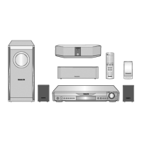
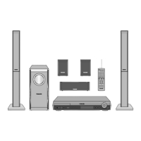
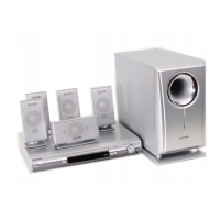
| Type | Home Theater System |
|---|---|
| Audio Channels | 5.1 |
| DVD Player | Yes |
| HDMI Outputs | 1 |
| USB Port | Yes |
| Surround Sound Formats | Dolby Digital, DTS |
| Progressive Scan | Yes |
| Remote Control | Yes |
| Playable Media | DVD, CD, MP3 |
| Inputs | Analog Audio |
| Outputs | HDMI |
| Tuner | FM |
| Total Power Output | 600 Watts |