EasyManua.ls Logo

Panasonic SA-HT640WP User Manual

Panasonic SA-HT640WP
120 pages
To Next Page IconTo Next Page
Page #1 background imageLoading...
Page #1 background image
lGeneral
Power Source:
A
C 120V, 60Hz
Power consumption: 85 W
Dimensions (W×H×D): 430×70×439.2 mm
(16-15/16”×2-3/4”×17-19/64”)
Mass:
4.65 kg (10.25Ibs)
lAmplifier section
RMS Output Power: Dolby Digital Mode
lTotal RMS Dolby Digital
mode Power:
850 W
At 1kHz and total harmonic of 10%
lFront: 110 W/ Channel (3)
lCenter: 225 W/ Channel (6)
lSurround: 90 W/ Channel (4)
At 100Hz and total harmonic of 10%
lActive subwoofers: 225 W/ Channel (6)
FTC Output Power: Dolby Digital Mode
lTotal FTC Dolby Digital mode Power:
300 W
At 120Hz-20kHz and total harmonic of 1%
lFront: 40 W/ Channel (3)
lCenter: 75 W/ Channel (6)
lSurround: 40 W/ Channel (4)
© 2006 Panasonic AVC Networks Singapore Pte.
Ltd. All rights reserved. Unauthorized copying and
distribution is a violation of law.
SA-HT640WP
SA-HT640WPC
Colour
(S).......................Silver Type
At 45Hz-120Hz and total harmonic of 1%
lSubwoofer: 65 W/ Channel (6)
lFM tuner section
Preset Memory:: FM 15 stations
AM/MW 15 stations
Frequency Range:
87.9-107.9MHz
(200kHz in step)
87.5-108.0MHz
(100kHz in step)
Sensitivity: 2.5µV (IHF)
S/N 26dB
2.2µV
Antenna Terminals: 75 (unbalanced)
lAM tuner section (AM/MW)
Frequency Range: 520-1710kHz (10kHz in step)
AM Sensitivity S/N 20dB at
1000kHz:
560µV/m
lPhone Jack:
Terminal: Stereo 3.5 mm (1/8”) jack
lFront/Rear M. Port:
Sensitivity: 100mV (4.7k)
Terminal (Input): Stereo 3.5 mm (1/8”) jack
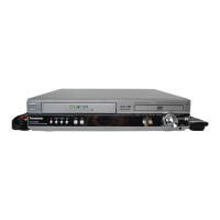
lDisc section
Discs played [8 cm (3”) or 12 cm (5”)]:
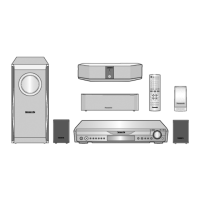
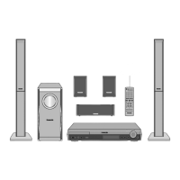
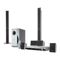
DVD Home Theater Sound System
Specifications
ORDER NO.MD0512492C1
A6

Table of Contents

Questions and Answers:

Panasonic SA-HT640WP Specifications

General IconGeneral
BrandPanasonic
ModelSA-HT640WP
CategoryHome Theater System
Total Output Power1000 W
Number of Channels5.1
Number of Speakers6
DVD PlayerYes
HDMI Inputs2
USB PlaybackYes
Surround Sound FormatsDolby Digital, DTS
Progressive ScanYes
DTS DecoderYes
USB Port1
HDMI Output1
BluetoothNo
Remote ControlYes
Speaker TypeSatellite
SubwooferYes
Audio Output Power100 W

Summary

Specifications

General

General specifications including power, dimensions, and mass.

Amplifier section

Details on RMS output power, total power, and frequency response.

FM tuner section

FM tuner specifications including preset memory, frequency range, and sensitivity.

AM tuner section

AM tuner specifications including frequency range and sensitivity.

Safety Precautions

GENERAL GUIDELINES

General guidelines to be followed during servicing and operation.

Before Repair and Adjustment

Precautions to take before performing repairs or adjustments.

Protection Circuitry

Explanation of the unit's protection circuitry and its operation.

Prevention of Electro Static Discharge (ESD) to Electrostatically Sensitive (ES) Devices

Precaution of Laser Diode

Handling Precautions for Traverse Unit

Cautions to Be Taken in Handling the Optical Pickup Unit

Cautions for handling the optical pickup unit to prevent damage.

Grounding for electrostatic breakdown prevention

Procedures for grounding to prevent electrostatic discharge damage.

Operation Procedures

Operating instructions

Instructions on how to operate the unit using the remote control.

Remote Control Key Buttons Operations

Explanation of the functions of the remote control key buttons.

Main Unit Key Buttons Operations (SA-HT640W)

Explanation of the functions of the main unit's key buttons.

Wireless Surround Speaker Key Buttons Operations (SB-SA640)

Explanation of the buttons on the wireless surround speaker unit.

Disc information

Information about the types of discs supported and cleaning procedures.

New Features

RF Wireless Audio Transceiver

Details about the RF wireless audio transceiver system.

Features

Key features of the RF wireless audio transceiver.

Class-D Amplifier

Explanation of Class-D amplifier technology and its benefits.

What are the potential problems of a Class-D amplifier based system?

Potential problems associated with Class-D amplifier systems.

Self-Diagnosis and special mode setting

Service Mode Summary Table

Summary table of service modes and their applications.

Optical Pick-up Self-Diagnosis

Procedure for optical pickup self-diagnosis and tilt adjustment.

DVD Self Diagnostic Function-Error Code

List of error codes for the DVD self-diagnostic function.

Assembling and Disassembling

Disassembly Flow Chart

Flowchart illustrating the disassembly sequence of the unit.

Main Components and P.C.B. Locations

Diagram showing the locations of main components and PCBs.

Disassembling the Top Cabinet

Step-by-step instructions for disassembling the top cabinet.

Disassembling the Front Panel Assembly

Step-by-step instructions for disassembling the front panel assembly.

Disassembling the Tray Assembly

Step-by-step instructions for disassembling the tray assembly.

Disassembling the Rear Panel

Step-by-step instructions for disassembling the rear panel.

Disassembling the Mechanism Base Assembly

Step-by-step instructions for disassembling the mechanism base assembly.

Disassembling the FL & Head phone P.C.B.

Step-by-step instructions for disassembling the FL and headphone PCB.

Disassembling the Main P.C.B.

Step-by-step instructions for disassembling the main PCB.

Measurements and Adjustments

Service Tools and Equipment

List of service tools and equipment for measurements and adjustments.

Important points in adjustment

Important points to consider before and during adjustment procedures.

Important points in optical adjustment

Key considerations for optical adjustment procedures.

Storing and handling of test discs

Guidelines for storing and handling test discs.

Optical adjustment

Procedures for performing optical adjustments.

Optical pickup tilt adjustment

Detailed procedure for optical pickup tilt adjustment.

Adjustment procedure

Step-by-step guide for performing the optical adjustment.

Abbreviations

Voltage and Waveform Chart

DVD Module P.C.B.

Voltage measurements for various points on the DVD Module PCB.

Main P.C.B.

Voltage measurements for various points on the Main PCB.

Power P.C.B.

Voltage measurements for various points on the Power PCB.

FL P.C.B.

Voltage measurements for various points on the FL PCB.

Waveform Chart

Illustration of IC's, Transistors and Diodes

Wiring Connection Diagram

Block Diagram

Schematic Diagram

Notes:

Notes regarding modifications and voltage measurements in schematic diagrams.

Caution!

Safety precautions when working with ICs and LSIs.

(A) DVD Module Circuit

(B) Main Circuit

(C) Power Circuit

(D) FL and Headphone Circuit

(E) Loading Motor, Tray Motor and Sensor Circuit

Printed Circuit Board

(A) DVD Module P.C.B. (REP4080A)

Printed circuit board layout for the DVD module (Side A and B).

(B) Main, AC-Inlet & Sub Power P.C.B.

Printed circuit board layouts for the Main, AC-Inlet, and Sub Power PCBs.

(C) Power P.C.B.

Printed circuit board layout for the Power PCB.

(D) FL, Headphone, Loading motor, Tray motor, Sensor and Regulator P.C.B.

Printed circuit board layouts for FL, Headphone, Loading motor, Tray motor, Sensor, and Regulator PCBs.

Basic Troubleshooting Guide

Basic Troubleshooting Guide for DVD Module

Guide for troubleshooting issues with the DVD module's firmware and key download.

Firmware and Key Download

Troubleshooting steps for firmware and key download failures.

Initialisation and playability

Troubleshooting guide for initialization and playability problems.

Basic Troubleshooting Guide for Traverse Unit

Troubleshooting Guide for Wireless Surround Speaker (SB-SA640)

Troubleshooting for digital receiver unit (SB-SA640)

Troubleshooting steps for the digital receiver unit of the wireless system.

Troubleshooting for digital amp circuit (Step By Step guide)

Step-by-step troubleshooting guide for the digital amplifier circuit.

Overall Block Diagram for HT640

SC-HT640 DVD Unit Block Diagram

Block diagram specific to the SC-HT640 DVD unit.

Service parts replacement

Information on replacing service parts.

Transmitter Assembly (RFKVHFX60PPS)

Details on replacing the transmitter assembly.

Terminal Function of ICs

IC2001 (MN101C49GHG): Micro-processor IC

Pin assignments and functions for the MN101C49GHG micro-processor.

Explode Views

Cabinet Parts Location

Exploded view showing the location of cabinet parts.

Packaging

Replacement Parts List

Notes:

Important notes regarding safety, part specifications, and markings.

Component Parts List

Detailed list of all component parts for replacement.

Related product manuals