EasyManua.ls Logo

Panasonic SB-VK72

Panasonic SB-VK72
148 pages
To Next Page IconTo Next Page
Loading...
AMPLIFIER SECTION
RMS Output Power: Dolby Digital Mode
Main
70 W per channel (6 ), 1 kHz, 10% THD
Surround Ch
55 W per channel (6 ), 1 kHz, 10% THD
Center Ch
70 W per channel (6 ), 1 kHz, 10% THD
Total RMS Dolby Digital mode power
320 W
FM/AM TUNER, TERMINALS SECTION
Preset station FM 15 stations
AM 15 stations
Frequency Modulation (FM)
Frequency range 87.50 - 108.00 MHz (50 kHz step)
Sensitivity 2.5 µV (IHF)
S/N 26 dB 2.2 µV
A
ntenna terminals 75 (unbalanced)
A
mplitude Modulation (AM)
Frequency range 522 - 1629 kHz (9 kHz step)
A
M Sensitivity S/N 20 dB at 999 kHz
560 µV/m
A
udio performance (Amplifier)
Input sensitivity/Input impedance
A
ux 250 mV, 20 k
© 2005 Matsushita Electric Industrial Co. Ltd.. All
rights reserved. Unauthorized copying and
distribution is a violation of law.
SA-VK725DEE
Colour
(S)... Silver Type
Phone jack
Terminal Stereo, 3.5 mm jack
Mic jack
Sensitivity 0.7 mV, 600
Terminal Mono, 6.3 mm jack (2 system)
CASSETTE DECK SECTION
Type Auto-Reverse
Track system 4-Track, 2 Channel
Head Record/Playback Solid permalloy head
Erasure Double gap ferrite head
Motor DC servo moto
r
Recording System AC Bias 100 kHz
Erasing System AC Erase 100 kHz
Tape Speed 4.8 cm/s
Overall frequency response (+3, -6 dB) at DECK OUT
Normal 35 Hz - 14 kHz
S/N Ratio 50 dB (A weighted)
Wow and Flutter 0.18 % (WRMS)
Fast Forward and Rewind Time Approx. 120 seconds with
C-60 cassette tape
DISC SECTION
Disc played [8 cm or 12 cm]
(1) DVD (DVD-Video, DVD-Audio, DivX
*6
,
*7
)
(2) DVD-RAM (DVD-VR, JPEG
*4
,
*7
, MPEG4
*5
,
*7
,DivX
*6
,
*7
)
DVD Stereo System
Specifications
ORDER NO. MD0507277C3

Table of Contents

Question and Answer IconNeed help?

Do you have a question about the Panasonic SB-VK72 and is the answer not in the manual?

Panasonic SB-VK72 Specifications

General IconGeneral
BrandPanasonic
ModelSB-VK72
CategoryCD Player
LanguageEnglish

Summary

Specifications

Amplifier Section

Details of amplifier output power, modes, and channels.

FMAM Tuner, Terminals Section

Specifications for FM/AM tuner, including sensitivity and terminals.

Cassette Deck Section

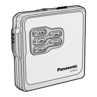
Details on cassette deck type, track system, head, motor, and tape speed.

Disc Section

Information about supported disc types and sizes.

General Specifications

Power, Dimensions, and Environment

General specifications including power, dimensions, mass, and environmental conditions.

Before Repair and Adjustment

Protection Circuitry

Safety Precautions

General Servicing Guidelines

General rules to follow during servicing for safety and proper procedure.

Leakage Current Checks

Procedure for checking leakage current when the unit is unplugged.

ESD Prevention

Lead-Free Solder Handling

About Lead-Free Solder (PbF)

Information on identifying and handling lead-free solder PCBs.

Laser Diode Precautions

Optical Pickup Handling Cautions

Handling and Replacing Optical Pickup

Guidelines for handling the optical pickup unit itself.

Grounding for ESD Prevention

Procedures for grounding to prevent ESD damage to the optical pickup.

Operation Procedures

Control Reference Guide

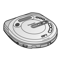
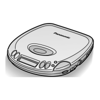
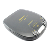
Overview of the unit's controls and functions.

Remote Control Operations

Disc Information

Optical Pickup Diagnosis and Replacement

Optical Pickup Breakdown Diagnosis

Methods for diagnosing issues with the optical pickup.

Self-Diagnosis Function

Entering Diagnostic Mode

Steps to activate the self-diagnosis mode.

Error Code Handling

Explanation of error codes displayed automatically.

Automatic and Memorized Error Codes

How to access and display previously stored error codes.

Service Modes and Error Codes

Re-Displaying Errors and Service Tables

How to re-display memorized self-diagnosis results.

DVDCD Self-Diagnosis Error Codes

Detailed table of error codes, their states, causes, and troubleshooting.

Mode Tables

Table detailing various player modes accessible via button combinations.

Self-Diagnosis Mode Details

Self-Diagnosis Mode Details (Continued)

Special Service Modes

CR16 Mechanism Ageing Mode

Procedure for activating and performing the CR16 mechanism ageing process.

Operation Lock Function

How to set and use the operation lock feature to prevent unauthorized use.

Post-Repair Procedures and Cautions

After Repair Steps

Steps to perform after completing repairs on the unit.

Servicing Cautions and Firmware Upgrade

Important cautions to observe while servicing the unit.

Recovery and Upgrade Procedures

Using Recovery Disc

Instructions on how to use the recovery disc for system renewal.

Disassembly and Assembly of Main Components

Disassembly Steps Index

An index listing the various parts and components that can be disassembled.

Disassembly Flow Chart

Component Disassembly Procedures

Top Cabinet, Rear Panel, DVD Changer Unit

Step-by-step instructions for removing the top cabinet, rear panel, and DVD changer.

PCB Disassembly Procedures

Power PCB Disassembly

Transformer and Front Panel Disassembly

MicPanel PCB and Lid Disassembly

Deck Mechanism and Traverse Deck Procedures

Optical Pickup Unit Replacement

Mechanism Disassembly and Replacement

Traverse Deck Replacement

CD Loading Unit Disassembly

CR16 Mechanism Assembly

Traverse Unit Disassembly

Cassette Lid Replacement

Tape Jam Problem Rectification

Major PCB Checking Procedures

Transformer PCB Checking

Panel, Deck, and Mechanism PCB Checking

Power PCB Checking

Measurements and Adjustments

Tuner Section Alignment

Alignment Points

Block Diagram

Voltage Measurement

Schematic Diagrams

Optical Pickup Unit Circuit

DVD Module Circuit Schematics

DVD Module Circuit Schematics (Continued)

Main (Tuner) Circuit Schematic

Main Circuit Schematics

Main Circuit Schematics (Continued)

Panel and Mic Circuit Schematics

Panel Circuit Schematics (Continued)

Deck and Deck Mechanism Circuit Schematics

Deck Circuit Schematics (Continued)

Power Circuit Schematic

Power Amp Circuit Schematic

Transformer Circuit Schematic

CD Loading Circuit Schematic

Printed Circuit Board Layouts

Printed Circuit Board Layouts (Continued)

Main PCB Layout

Panel PCB Layout

Deck PCB Layouts

Power PCB Layouts

Transformer PCB Layout

CD Loading PCB Layout

Wiring Connection Diagram

Component Illustrations

IC Terminal Functions

IC Terminal Functions (Continued)

Parts Location and Replacement Parts List

Deck Mechanism Parts Location

Deck Mechanism Parts List

DVD Loading Mechanism Parts Location

DVD Loading Mechanism Parts List

Cabinet Parts Location

Cabinet and Electrical Parts Lists

Electrical Parts List

Comprehensive list of all electrical components including ICs, transistors, and diodes.

Related product manuals