Wireless connections (optional)
Connecting the speakers with the optional wireless system (SH-FX70:2 units)
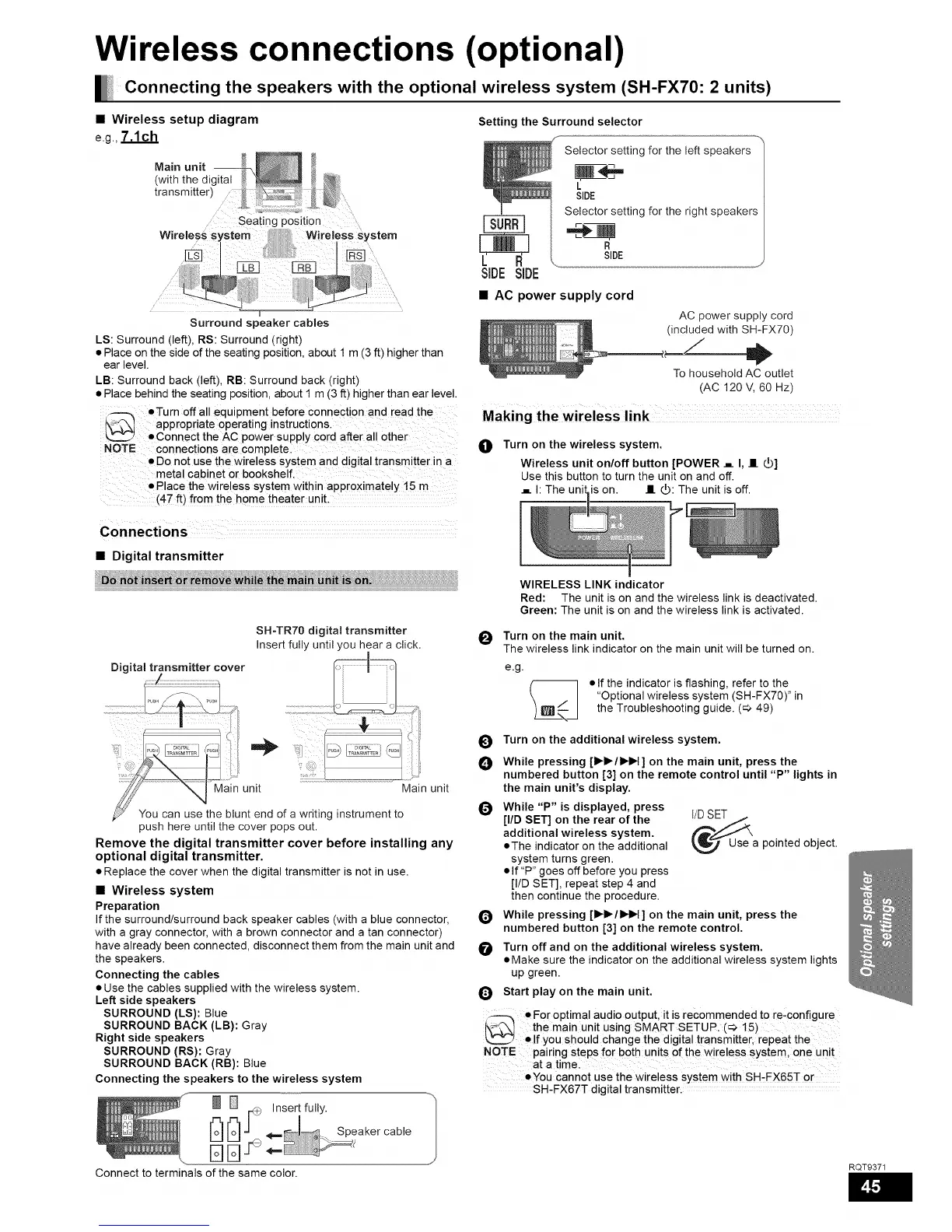
• Wireless setup diagram
e.g.,7.1ch
Main unit --
(with the digital
transmitter)
Surround speaker cables
LS: Surround (left), RS: Surround (right)
• Place on the side of the seating position, about 1 m (3 ft) higher than
ear level.
LB: Surround back (left), RB: Surround back (right)
• Place behind the seating position, about I m (3 ft) higher than ear level.
_--_ •Turn off all equipment before connect on and read the
l\-_ appropriate operating instructi0ns.
L2Z_2 • Connect the AC power supply cord after all other
NOTE connections are completel
• Do not use the wireless system and digital transmitter in a
metal cabinet or bookshelf,
Place the wireless system within approximately 15 m
(4-7 ft) fro m the home theater unit:
Setting the Surround selector
Selector setting for the left speakers
L
SIDE
Selector setting for the right speakers
SIDE
SIDE SIDE
• AC power supply cord
AC power supply cord
(included with SH-FX70)
To household AC outlet
(AC 120 V, 60 Hz)
Making the wireless link
O
Turn on the wireless system.
Wireless unit on/off button [POWER ._ I, II _]
Use this button to turn the unit on and off.
._ h The unil is on. II _: The unit is off.
• Digital transmitter
:_il !t_in !ni_;i _': ii;i;i;i;i;i;i;i;i;i;i;i;i;i;i;i;i;i;i
SH-TR70 digital transmitter
Insert fully until you hear a click.
Digital transmitter cover _1_
.................................._u_H .........................................................i_
..... .... ii"i
_Maln unit _ JMam unit
blunt end of a writing instrument to
push here until the cover pops out.
Remove the digital transmitter cover before installing any
optional digital transmitter.
• Replace the cover when the digital transmitter is not in use.
• Wireless system
Preparation
If the surround/surround back speaker cables (with a blue connector,
with a gray connector, with a brown connector and a tan connector)
have already been connected, disconnect them from the main unit and
the speakers.
Connecting the cables
• Use the cables supplied with the wireless system.
Left side speakers
SURROUND (LS): Blue
SURROUND BACK (LB): Gray
Right side speakers
SURROUND (RS): Gray
SURROUND BACK (RB): Blue
Connecting the speakers to the wireless system
_ r_+_ Insert fully.
[r_[r_J" _ Speakercable
Connect to terminals of the same color.
WIRELESS LINK indicator
Red: The unit is on and the wireless link is deactivated.
Green: The unit is on and the wireless link is activated.
_11 Turn on the main unit.
v
The wireless link indicator on the main unit will be turned on.
e.g.
%
• If the indicator is flashing, refer to the
"Optional wireless system (SH-FX70)" in
the Troubleshooting guide. (_ 49)
O
O
Q
Q
O
Turn on the additional wireless system.
While pressing [l_l_/l_H ] on the main unit, press the
numbered button [3] on the remote control until "P" lights in
the main unit's display.
While "P" is displayed, press
[liD SET] on the rear of the
additional wireless system.
• The indicator on the additional
system turns green.
• If "P" goes off before you press
[I/D SET], repeat step 4 and
then continue the procedure.
Use a pointed object.
While pressing [l_l_/l_H ] on the main unit, press the
numbered button [3] on the remote control.
Turn off and on the additional wireless system.
• Make sure the indicator on the additional wireless system lights
up green.
Start play on the main unit.
• For optimal audio output, it is recommended to re,configure
{\_L'_I the main unit using SMART SETUP. (_ 15)
',._ • If you should change the digital transmitter, repeat the
NOTE pairing steps for both units of the wireless system one unit
at a timel
• You cannot use the wireless sYstem with SH,FX65-F or
SH-FX67T digital transmitter.
RQT9371