Do you have a question about the Panasonic SC-H M900 and is the answer not in the manual?
Procedures for testing insulation resistance to prevent shock hazards.
Precautions for handling the traverse deck and its components.
Methods for grounding to prevent electrostatic discharge during service.
Step-by-step guide for replacing the traverse deck unit.
Procedures for removing and installing the traverse unit.
Steps for installing the disc tray after replacement.
Instructions on how to activate the self-diagnostic mode.
Test procedure for cassette mechanism errors.
Step-by-step instructions to enter CD test mode.
How to interpret auto-adjustment results shown on the FL display.
Measurements and adjustments for the cassette deck section.
Procedure for adjusting head azimuth on both decks.
Procedure for adjusting tape speed on both decks.
Alignment procedure for the AM Intermediate Frequency circuit.
PCB layout for the Deck 1 mechanism.
| Brand | Panasonic |
|---|---|
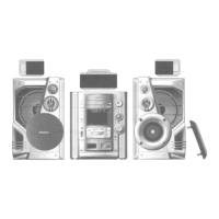
| Model | SC-H M900 |
| Category | Stereo System |
| Language | English |