Connector or cable to be used varies depending on the upper communication unit
(SC-GU3-0
, SC-GU1-485
,
or
SC-GU2-C) to be used in combination with the prod-
uct. For details, refer to the instruction manual enclosed with the upper communica-
tion unit.
Cascading method
Ɣ Below is indicated an example of using the upper communication unit (SC-GU3-
0
).
1. Mount the communication unit
SC-GU3-0
to the DIN rail.
When doing this, remove the
end connector cap from the joint
connector part of this product.
2. Mount the joint connector unit
SC-71 one by one to the DIN
rail, and slide them toward the
SC-GU3-0
.
Slide
Open network communication
unit SC-GU3-0
Joint connector unit SC-71 (optional)
End
Connector
cap
3. Insert this product SC-A0
into
SC-71.
Insert
SC-A0
Joint connector unit SC-71 (optional)
4. Mount the end unit SC-GU3-EU
(optional) to the DIN rail, and
slide it toward the sensor ampli-
¿HU
5. Attach the
end connector cap
,
which was removed in 1 above,
to the joint section of the unit at
WKH¿QDOHQG
Slide
End unit SC-GU3-EU (optional)
End connector
cap
6.
Mount the
end plates MS-DIN-
E (optional)
at both ends to hold
WKHXQLWVEHWZHHQWKHLUÀDWVLGHV
7.
Tighten the screws to fix
MS-
DIN-E.
End plate MS-DIN-E (optional)
End plate MS-DIN-E (optional)
Dismantling method
1. Loosen the screws of MS-DIN-E.
2. Remove MS-DIN-E.
3. Slide SC-71 one by one, and
remove the connector.
4. Remove each unit.
Pull out
Release
lever
7 I/O CIRCUIT DIAGRAM
<SC-A01>
Analogue
voltage input
+V
NPN input
0V
Terminal No. of
input device side
Input
device side
Internal
circuit
To external
connection
Nȍ
Nȍ
A/D conver-
sion circuit
Main circuit
+V
Output
0V
Terminal No. of
power supply side
<SC-A02>
Input
device side
Internal
circuit
To external
connection
Analogue
current input
Terminal No. of
input device side
+V
NPN input
0V
+V
Output
0V
Terminal No. of
power supply side
A/D conver-
sion circuit
Main circuit
Nȍ
Nȍ
ȍ
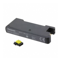
INSTRUCTION MANUAL
Upper Communication Input Unit SC Series
For analogue
voltage input
For analogue
current input
SC-A01 SC-A02
MJE-SCA01 No.0095-29V
Thank you very much for purchasing Panasonic products.
Read this Instruction Manual carefully and thoroughly for the correct and optimum
use of this product.
Kindly keep this manual in a convenient place for quick reference.
WARNING
Never use this product in a detection device for personnel protection.
Be sure to use this product in combination with SC-GU-3-0
, SC-GU1-485
, and
SC-
GU2-C (optional). This product cannot be used alone.
For details, refer to the instruction manual enclosed with SC-GU-3-
0
, SC-
GU1-485, SC-GU2-C.
1 OUTLINE
Ɣ This product is an input/output unit which can be used in combination with the up-
per communication unit (SC-GU3-
0
, SC-GU1-485, SC-GU2-C).
Ɣ An output device of NPN output type or analogue voltage/current output type can
be connected to this product.
Ɣ This product has resolution of 1/4,000 (12 bits).
Ɣ The analogue input range is 1 to 5V for SC-A01, and 4 to 20mA for SC-A02.
2 PART DESCRIPTION
<SC-A01, SC-A02>
CONNECTION
4
Brown: +V
Black: OUT
Blue: 0V
SC-A01
2
1
3
DIN +V 0V AIN
INPUT
POWER
1: Input indicator (Green)
2: Power indicator (Green)
Designation Function
1 Input indicator (Green) Lights up when NPN input is ON.
2 Power indicator (Green) Lights up when power is ON.
3 MOUNTING
Mounting method
1. Press down the rear part of the mounting section
of the joint connector unit SC-71 (optional)
on the
',1UDLODQG¿WWKHIURQWSDUWRIWKHPRXQWLQJVHFWLRQ
into the DIN rail.
Joint connector unit
SC-71
1
2
35mm width DIN rail
2. Insert this product SC-A0
into SC
-71.
SC-A0
Removing method
1.
While holding this product SC-A0
,
and pressing
the release lever, pull out the product from SC
-71.
SC-A0
Release
lever
1
2. Push the rear part of the mounting section of SC-71
forward.
3. Lift up the front part of the unit to remove it.
3
2
Note:
Take care that if the front part is lifted without pushing the joint connector unit forward, the hook on the rear portion
of the mounting section is likely to break.
4 CONNECTION
<Connection of the connector CN-EP2 (enclosed)>
Ɣ Make sure to connect or disconnect the connector CN-EP2 in the power supply
RႇFRQGLWLRQ
Ɣ Names of connector (enclosed) parts
Release lever
1
2
3
4
Wire inlet
<Terminal arrangement>
Terminal No. Terminal name
1+V
2 Analogue input
30V
4 Digital input
Ɣ Applicable wire
• 0.1 to 0.5mm
2
(AWG27 to 20)
1RWHWKDWWKHZLUHVKHDWKGLDPHWHUVKRXOGEHijWRijPP
Precautions for wire connection
Ɣ 'RQRWSHHORႇWKHZLUHVKHDWK
Ɣ Check the connection terminal arrangement before wiring.
Wire connection
1. 3URFHVVWKHFDEOHDVLOOXVWUDWHGEHORZ'RQRWSHHORႇWKHVKHDWK
20mm or more
Wire
2. Insert the wire to the wire inlet of the connector, until the tip of the wire contacts
the innermost wall.
Wire
Insert until the tip contacts the wall
3. Pressure weld the connector using a plier or the like.
• For pressure welding, make sure to apply the plier in parallel with the connector,
from the direction indicated below.
• Pay attention not to damage the wire with the plier while pressure welding.
• Make sure that the wire does not become loose while pressure welding.
Plier
4. Slightly pull the wire to ensure that wire is not loose.
1RWH 'RQRWUHXVHDFRQQHFWRUDIWHUSUHVVXUHZHOGLQJ6SHFL¿FDWLRQVFDQQRWEHJXDUDQWHHG
Purchase an optional connector CN-EP2¿YHSLHFHVRUDUHFRPPHQGHGFRQQHFWRU
<Recommended connector>
e-CON: 1473562-4
[Made by Tyco Electronics Japan G.K.]
Connection method
1. Insert the input connector into the inlet of the unit till a click is felt.
Input connector
Disconnection method
1. Pressing the release lever at the top of the input connector, pull out the connector.
Release lever
Note: Take care that if the connector is pulled out without pressing the release lever, the release lever may break. Do
not use an input connector whose release lever has broken. Further, do not pull by holding the cable, as this can
cause a cable-break.
5 WIRING
Make sure to turn OFF the power before connecting or disconnecting the quick-
connection cable or wire-saving connector.
2
1
3
Terminal No. Terminal name
1+V
2 Output
30V
Ɣ For how to handle the quick-connection cable or wire-saving connector, refer to
the enclosed instruction manual.
6 CASCADING UNITS
Ɣ Make sure to add or remove the units in the
SRZHUVXSSO\RႇFRQGLWLRQ
Ɣ Make sure to check the allowable ambient tem
-
perature, as it depends on the number of units
connected in cascade.
Ɣ In case 2 or more units are connected in cas-
cade, make sure to mount them on a DIN rail.
Ɣ Up to maximum 16 units can be added.
Ɣ When this product and other products (e.g.
fiber sensor amplifiers, laser sensor ampli-
¿HUVHWFDUHFRQQHFWHGWRJHWKHULQFDVFDGH
install those products so that they are in order
of Group A, B, D and C as shown in the right
¿JXUH7KLVSURGXFWLVLQFOXGHGLQ*URXS&
Ɣ Within each group, identical models should be
connected in a lump.
Communication direction
Group
A
Group
B
Group
D
Group
C
Group Applicable Model
A
FX-301
(conventional version)
FX-301B
/G
/H
, LS-401
B
FX-301
PRGL¿HGYHUVLRQ
FX-305
C
LS-403
, DPS series
SC-A0
, SC-T1JA
D FX-500 series
8 CAUTIONS
Ɣ This product has been developed / produced for industrial use only.
Ɣ Make sure that the power supply is OFF while wiring and adding the units.
Ɣ Take care that if a voltage exceeding the rated range is applied, or if an AC power
supply is directly connected, the product may get burnt or damaged.
Ɣ Make sure to check the wiring as wrong wiring can damage or burn the product.
Ɣ Do not run the wires together with high-voltage lines or power lines or put them in
the same raceway. This can cause malfunction due to induction.
Ɣ 7KHVSHFL¿FDWLRQPD\QRWEHVDWLV¿HGLQDVWURQJPDJQHWLF¿HOG
Ɣ Verify that the supply voltage variation is within the rating.
Ɣ If power is supplied from a commercial switching regulator, ensure that the frame
ground (F.G.) terminal of the power supply is connected to an actual ground.
Ɣ Take care that if noise is applied to the analogue voltage input, the product may
malfunction.
Ɣ Make sure to use an insulation transformer for DC power supply. If an auto-trans-
former (single winding transformer) is used, the main body or the power supply
may get damaged.
Ɣ In case a surge is generated in the used power supply, connect a surge absorber
to the supply and absorb the surge.
Ɣ Do not use the unit during the initial transient time (approx. 0.5 sec.) after the
power supply is switched on.
Ɣ In order to reduce noise, make the wiring as short as possible.
Ɣ This product is suitable for indoor use only.
Ɣ Avoid dust, dirt, and steam.
Ɣ Take care that the product does not come in contact with oil, grease, organic sol-
vents, such as thinner, etc., strong acid or alkaline.
Ɣ 7KLVSURGXFWFDQQRWEHXVHGLQDQHQYLURQPHQWFRQWDLQLQJLQÀDPPDEOHRUH[SOR-
sive gases.
Ɣ Never disassemble or modify the product.
9 SPECIFICATIONS
Designation Upper Communication Input Unit
Model No. SC-A01 SC-A02
Supply voltage 12
to 24V DC±10% Ripple P-P 10% or less
Current consumption Max. 25mA or less (when all indicators light up and 24V is applied) (Note 1)
Analogue voltage input
(
Input impedance)
1 to 5V DC
$SSUR[Nȍ
4 to 20 mA DC
$SSUR[ȍ
Communication data
(Note 2)
Analogue
Communication data
Communication data: 0 to 4,000 digits
(within the range of 1 to 5V)
Zero point : Within 0 digit ±0.5% F.S.
Span : Within 4,000 digits ±0.5%
F.S .
Linearity : Within ±0.5% F.S.
Analogue
Communication data
Communication data: 0 to 4,000 digits
(within the range of 4 to 20mA)
Zero point : Within 0 digit ±0.5% F.S.
Span : Within 4,000 digits ±0.5%
F.S .
Linearity : Within ±0.5% F.S.
Input
Connectable device: Output type of NPN open-collector transistor
Supply current for input device: 100mA or less
,QSXWLPSHGDQFH$SSUR[Nȍ
Operating voltage: 17V or more at ON voltage (between input and +V at 24V)
4V or less at OFF voltage (between input and +V at 24V)
Output
NPN open-collector transistor
Maximum sink current: 50mA (Note 3)
• Applied voltage : 30V DC or less (between output and 0V)
• Residual voltage : 1.5V or less (at 50mA sink current) (Note 4)
Ambient temperature
(Note 6)
-10 to +55ºC (If 4 to 7 units are connected in cascade: -10 to +50ºC, if 8 to 16 units are
connected in cascade: -10 to +45ºC) (No dew condensation or icing allowed), Storage: -20 to
+70ºC
Ambient humidity 35 to 85% RH, Storage: 35 to 85% RH
Material
Enclosure: Flame retardant PBT
Weight Approx. 15g
Accessory Input connector: 1 pc.
Notes: 1) The current consumption and input current of
connected input units are not included.
2) Relationship between communication data and
input voltage and input current is as shown in
WKHULJKW¿JXUH
3)
25mA, when cascading 5 or more units.
4) This is the value to which the quick-connection
cable CN-71-
(optional) is attached. Not in-
cluding extension of the cable.
7KHDERYHVSHFL¿HGYDOXHVDUHDSSOLHGWRWKH
product itself. As for an output device that is
used in combination with this product, refer to
the instruction manual enclosed with the output
device.
6) Connected in cascade means number of units
for SC-GU3-0
, it not means number connec-
tor input for SC-A0
.
4,000
0
Input voltage/current
Communication data
5V
(20 mA)
1V
(4 mA)
Panasonic Industry Co., Ltd.
1006, Oaza Kadoma, Kadoma-shi, Osaka 571-8506, Japan
https://industry.panasonic.com/
Please visit our website for inquiries and about our sales network.
Panasonic Industry Co., Ltd. 2024
April, 2024 PRINTED IN JAPAN