EasyManua.ls Logo

Panasonic SCXH70 User Manual

Panasonic SCXH70
132 pages
To Next Page IconTo Next Page
Page #1 background imageLoading...
Page #1 background image
© Panasonic Corporation 2009. All rights reserved.
Unauthorized copying and distribution is a violation
of law.
PSG0910006CE
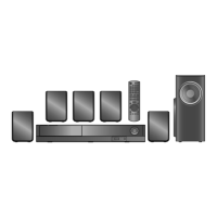
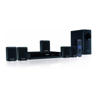
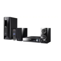
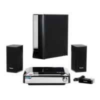
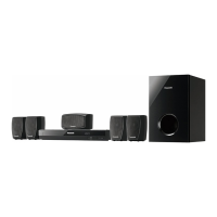
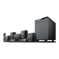
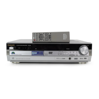
DVD Home Theater Sound System
Model No. SA-PT75PH
Product Color: (K)...Black Type
TABLE OF CONTENTS
PAGE PAGE
1 Safety Precautions----------------------------------------------- 3
1.1. GENERAL GUIDELINES-------------------------------- 3
1.2. Before Repair and Adjustment ------------------------- 3
1.3. Protection Circuitry---------------------------------------- 4
1.4. Safety Parts Information --------------------------------- 4
2 Warning-------------------------------------------------------------- 5
2.1. Prevention of Electrostatic Discharge (ESD)
to Electrostatic Sensitive (ES) Devices -------------- 5
2.2. Precaution of Laser Diode------------------------------- 6
2.3. Service caution based on Legal restrictions-------- 7
2.4. Handling Precautions for Traverse Unit-------------- 8
3 Service Navigation --------------------------------------------- 10
3.1. Service Information-------------------------------------- 10
4 Specifications---------------------------------------------------- 11
5 Location of Controls and Components------------------ 13
5.1. Remote Control Key Button Operations------------ 13
5.2. Main Unit Key Button Operations-------------------- 14
5.3. Speaker Connection------------------------------------- 14
5.4. Using the VIERA Link “HDAVI Control™”---------- 15
5.5. Disc Information ------------------------------------------ 17
6 Self-Diagnosis and Special Mode Setting -------------- 19
6.1. Cold-Start -------------------------------------------------- 19
Note: Please refer to the original service manual for:
O DVD Mechanism Unit (DLS6E), Order No. PSG0909002AE
O Speaker system SB-PT70EG-K, Order No. PSG0909003CE

Table of Contents

Questions and Answers:

Panasonic SCXH70 Specifications

General IconGeneral
TypeHome Theater System
Power Output1000W
Number of Channels5.1
BluetoothYes
DVD PlaybackYes
USB PlaybackYes
Player TypeBlu-ray Player
3D PlaybackYes
Wireless Rear SpeakersNo
HDMI Outputs1
USB Ports1
Ethernet PortYes
NFCNo
Optical InputYes
FM TunerYes
Audio Formats SupportedDolby Digital, DTS

Summary

Safety Precautions

GENERAL GUIDELINES

General guidelines for safe servicing and post-service checks.

Before Repair and Adjustment

Precautions before starting repairs and adjustments.

Warning

Prevention of Electrostatic Discharge (ESD)

Techniques to prevent ESD damage to sensitive electronic components.

Precaution of Laser Diode

Safety precautions related to the laser diode in the optical pickup.

Service Navigation

Service Information

General information for service personnel regarding the manual.

Specifications

Location of Controls and Components

Remote Control Key Button Operations

Description of remote control button functions.

Main Unit Key Button Operations

Description of main unit button functions.

Self-Diagnosis and Special Mode Setting

Cold-Start

Procedure to perform a cold-start or initialize the unit.

Service Mode Table

Overview of service modes accessible via button combinations.

DVD Self Diagnostic Function-Error Code

Mechanism Error Code Table

Table of error codes related to mechanism operation.

DVD Module Error Code Table

Table of error codes specific to the DVD module.

Power Supply & Digital Amplifier Error Code Table

Error codes related to power supply and digital amplifier.

Troubleshooting Guide

Troubleshooting Guide for F61 and/or F76

Troubleshooting specific error codes F61 and F76.

Block Diagram

Block diagram illustrating F61/F76 error troubleshooting paths.

Troubleshooting Guide

Table of symptoms, checking items, and possible faults.

Disassembly and Assembly Instructions

Disassembly Flow Chart

Flowchart illustrating the disassembly sequence of components.

Main Components and P.C.B. Locations

Visual guide to the location of main components and PCBs.

Disassembly of Top Cabinet

Step-by-step instructions for removing the top cabinet.

Disassembly of DVD Module P.C.B.

Step-by-step instructions for removing the DVD module PCB.

Service Position

Checking & Repairing Main/D-Amp P.C.B. & Component Video P.C.B.

Procedures for checking and repairing Main/D-Amp and Component Video PCBs.

Checking & Repairing of SMPS P.C.B.

Procedures for checking and repairing the SMPS PCB.

Voltage & Waveform Chart

DVD Module P.C.B. (1/4)

Voltage values for DVD Module PCB (part 1 of 4).

Main P.C.B. (1/3)

Voltage values for Main PCB (part 1 of 3).

Waveform Table (1/3)

Waveform examples for various ICs (part 1 of 3).

Block Diagram

DVD(Servo)

Block diagram for the DVD servo system.

System Control

Block diagram of the system control functions.

Power Supply

Block diagram of the power supply circuits.

Wiring Diagram

Schematic Diagram

DVD Module Circuit

Schematic diagram of the DVD module circuit.

Main/D-Amp Circuit

Schematic diagram of the Main/D-Amp circuit.

SMPS Circuit

Schematic diagram of the SMPS circuit.

Printed Circuit Board

DVD Module P.C.B.

Printed circuit board layout for the DVD module.

Main/D-Amp P.C.B.

Printed circuit board layout for the Main/D-Amp module.

Terminal Function of ICs

IC200 (RFKWMPT75PHK): IC MICROPROCESSOR

Pin functions for the microprocessor IC.

IC901(C0HBB0000057): IC FL Driver

Pin functions for the FL driver IC.

Exploded View and Replacement Parts List

Mechanical Replacement Part List

List of mechanical replacement parts with safety references.

Electrical Replacement Part List

Related product manuals