Do you have a question about the Panasonic SP Series and is the answer not in the manual?
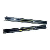
Provides detailed dimensional drawings for SP2 and SP4 terminal sockets, including measurements in mm and inches.
Illustrates the mounting hole layout for the SP terminal socket, specifying hole size and spacing for installation.
Details the procedure for mounting and removing the fastening bracket for SP terminal sockets, including required tools.
Presents the physical dimensions for the SP mounting board, including overall size and hole specifications.
Shows the mounting hole diagram for the SP mounting board, indicating hole sizes and panel cutout details.
Explains how to use the SP mounting board, covering direct chassis attachment and DIN rail mounting options.
Details the step-by-step method for mounting the SP mounting board onto a DIN rail, including fastening.
Advises on precautions for DIN rail mounting, specifically regarding the use of fastening brackets to prevent sliding.
This document describes the Panasonic SP Relays and their associated terminal sockets and mounting boards, designed for industrial applications.
The Panasonic SP Relays are designed to be used with specific terminal sockets (SP2-SF and SP4-SF) and mounting boards (SP-MA). These components facilitate the secure and organized installation of SP relays in control panels or other electrical enclosures. The terminal sockets provide an interface for wiring the relays, while the mounting boards offer flexible installation options, including direct chassis mounting and DIN rail mounting.
| Brand | Panasonic |
|---|---|
| Model | SP Series |
| Category | Accessories |
| Language | English |