1
MEUML-DP100 V1.1
Thank you for purchasing products from Panasonic Electric Works SUNX
Co., Ltd. Please read this Instruction Manual carefully and thoroughly for
the correct and optimum use of this product. Kindly keep this manual in a
convenient place for quick reference.
This product has been developed / produced for industrial use only.
Use within the rated pressure range.
Do not apply pressure exceeding the pressure resistance value. The
diaphragm will be damaged resulting in faulty operation.
Make sure that the power supply is off while wiring.
Incorrect wiring will damage the sensor.
Verify that the supply voltage including the ripple is within the rating.
If power is supplied from a commercial switching regulator, ensure that
the frame ground (F.G.) terminal of the power supply is connected to an
actual ground.
In case noise generating equipment (switching regulator, inverter motor,
etc.) is used in the vicinity of this sensor, connect the frame ground (F.G.)
terminal of the equipment to an actual ground.
Do not use during the initial transient time (0.5s) after the power supply is
switched on.
Do not run the wires together with high-voltage lines or power lines or put
them in the same raceway. This can cause malfunction due to induction.
The specification may not be satisfied in a strong magnetic field.
Avoid dust, dirt, and steam.
Take care that the sensor does not come in direct contact with water, oil,
grease, or organic solvents such as thinners, etc.
Do not insert wires, etc., into the pressure port. The diaphragm will be
damaged resulting in faulty operation.
Do not operate the keys with pointed or sharp objects.
Do not apply stress directly to the sensor cable joint by forcibly bending
or pulling.
.
Use a 12mm end wrench (14mm for DP-100-E type) when tightening a
commercial coupler to the pressure port. The tightening torque should be
9.8N·m or less (M5 female connector: 1N·m or less). The commercial
coupler or pressure port section will be damaged if the tightening torque is
excessive.
Wrap sealing tape around the coupler when connecting to prevent leaks.
INSTRUCTION MANUAL
WARNING
• Never use this product as a sensing device for personnel protection.
• In case of using sensing devices for personnel protection, use
products which meet laws and standards, such as OSHA, ANSI or
IEC etc., for personnel protection applicable in each region or
country.
• DP-100 series is designed for use with non-corrosive gas. It cannot
be used for liquid or corrosive gas.
• Japanese Measurement Laws prohibit the use of this product in
Japan.
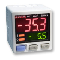
1 CAUTIONS
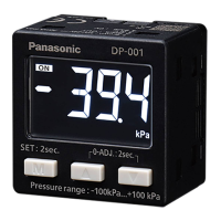
2 PART NAMES
No. Part Description
1 Output 1 opera-
tion indicator
Lights up when comparative output 1 is
ON
2 Output 2 / analog
voltage operation
indicator
• Standard type: lights up when
comparative output 2 is ON
• Multifunction type: lights up when
analog voltage output is ON
3 Pressure unit dis-
play
Depending on the model, “MPa” or “kPa”
appears here. If you set another pressure
unit, attach the appropriate label, e.g. psi,
bar, etc.
4 Main display Large 4-character LCD display.
5 Sub-display Small 4-character LCD display.
6 Mode selection
key
For details, see page 3, section 8,
SELECTING MODES.
7 Up key Increases value being set.
8 Down key Decreases value being set.
9 4-pin male con-
nector
See “Pin assignment, 4-pin male connec-
tor” on page 2.
0 Pressure port • DP-100 type: R1/8 + M5 female screw
• DP-100-E type: G1/8 + M5 female
screw
• DP-100-M type: M5 female screw
• DP-100-N type: NPT1/8 + M5 female
screw
3 PIPING
㧝
DP-100
1
0
9
876
5
4
3
2
12mm end wrench
Pressure Sensor
For use outside Japan
High-performance Digital Display
DP-100 Series
Rugghölzli 2
CH - 5453 Busslingen
Tel. +41 (0)56 222 38 18
Fax +41 (0)56 222 10 12
mailbox@sentronic.com
www.sentronic.com
Produkte, Support und Service
SEN
TRONIC
AG