INSTRUCTION MANUAL
Digital Fiber Sensor FX-100 series
MJE-FX100C No.0035-66V
Thank you very much for purchasing Panasonic products. Read this Instruction Manual
carefully and thoroughly for the correct and optimum use of this product. Kindly keep
this manual in a convenient place for quick reference.
WARNING
● Never use this product as a sensing device for personnel protection.
● In case of using sensing devices for personnel protection, use products which
meet laws and standards, such as OSHA, ANSI or IEC etc., for personnel protec-
tion applicable in each region or country.
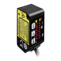
1 PART DESCRIPTION
Digital display (Green)
(Threshold value)
Digital display (Red)
(Incident light intensity)
MODE key
• Selection of setting items
• Conrmationofsetcontents
ON key / Set value UP key
• Selection of setting contents
• Settings in teaching mode
OFF key / Set value DOWN key
• Selection of setting contents
• Settings in teaching mode
Operation indicator
(Orange)
2 MOUNTING
<When using a DIN rail>
How to mount the amplier
1. Fittherearpartofthemountingsectionoftheamplier
on DIN rail.
2. Press down the rear part of the mounting section of the
unit on the
DINrailandtthefrontpartofthemounting
section to the DIN rail.
35mm width DIN rail
1
2
How to remove the amplier
1.
Pushtheamplierforward.
2.
Liftupthefrontpartoftheampliertoremoveit.
Note: Takecarethatifthefrontpartisliftedwithoutpushingtheamplierforward,
the hook on the rear portion of the mounting section is likely to break.
1
2
<When using screws with washers>
● Use M3 screws with washers for mounting. The tighten-
ing torque should be 0.5N·m or less.
M3 screw with
washer
How to connect the ber cable
Besuretottheattachmenttothebersrstbeforeinsertingtheberstotheampli-
er.Fordetails,refertotheInstructionManualenclosedwiththebers.
1. Incoveropencondition,snaptheberlockleverdown,
till it stops completely.
2. Insert the fiber cables slowly into the inlets until they
stop. (Note 1)
3. Returntheberlocklevertotheoriginalposition,tillit
stops.
Fiber
Fiber lock lever
1
3
2
Notes: 1) Incasetheber cablesarenot insertedto apositionwheretheystop, thesensingrangereduces. Sincea
exibleberiseasilybent,takecarewhenitisinserted.
2) Withthecoaxialreective typeber,suchas, FD-42G or FD-61G,insertthesingle-core bercable intothe
beam-emitting inlet “P”andthemulti-corebercableintothebeam-receivinginlet“D.” If they are inserted in
reverse, the sensing performance will deteriorate.
3 WIRING
Connection method
● Insert the cable with connector CN-14A-C□into this
product’sconnectorareaasshownintherightgure.
Cable with
connector
CN-14A-C
□
Disconnection method
● Pressing the release lever of the cable with connector,
pull out the connector.
Note: Take care that if the connector is pulled out without pressing the release
lever, cable or connector may break.
Cable with
connector
CN-14A-C
□
<Connector pin arrangement>
Connector pin No. Terminal name
1 +V
2 Output
3 Externalinput
4 0V
1
2
3
4
4 I/O CIRCUIT DIAGRAMS
NPN output type
+
12 to 24V DC
±10%
-
Main circuit
(Black) Output
(White)Externalinput
(Blue) 0V
Load
8V
Connector pin No.
(Brown) +V
Color code of cable with connector
*1
PNP output type
Load
*2
+
12 to 24V DC
±10%
-
(Black) Output
(White)Externalinput
(Blue) 0V
Connector pin No.
(Brown) +V
Color code of cable with connector
Main circuit
*1 *2
Non-voltage contact or NPN open-collector transistor
or
High (+8V to +V DC or Open): Invalid
Low [(0 to +2V DC (Source current 0.5mA or less)] : Valid
Non-voltage contact or PNP open-collector transistor
or
High [+4V to +V DC (Sink current 0.5 to 3mA or less)]: Valid
Low (0 to +0.6V DC or Open): Invalid
5 RUN MODE
<Digital display>
● When turning ON the power, the product name is indicated on the green digital dis-
play, while the emission frequency is indicated on the red digital display. Then switch-
es into RUN mode [digital display (green: threshold value, red: incident light intensity)].
AUTO
<When turning ON the power>
Emission
frequency
<RUN mode>
Product
name
Threshold
value
Incident light
intensity
● Whenselectingemissionhaltin theexternalinputsettingmodeandreceivingthe
signalexternally,“
” is indicated on the red digital display.
● WhenselectingECOintheexternalinputsettingmode,keyoperationonthemain
bodyisinvalidduringexternalinput.
● Whenselecting2-pointteachingintheexternalinputsettingmode,“
” is indi-
catedonthegreendigitaldisplayafterinputtingtherstpoint.
● WhenECOsettingmodeisON,the digitaldisplayturnsoffinapprox.20sec.In
case of lighting up the digital display again, press any key for 2 sec. or more.
● ForthesettingsofexternalinputandECO,referto“
PRO MODE.”
Threshold value ne adjustment function
● Fine adjustment of threshold value can be done when in RUN mode.
● Press the set value UP key or set value DOWN key to change threshold value.
(Hold down the key to make the value change faster.)
● The threshold value is stored after 3 sec.
Threshold
value
Incident light
intensity
When in RUN mode
Keylock function
● The keylock function prevents key operations so that the conditions set in each setting
mode are not inadvertently changed.
● In the keylock condition, “
” is displayed when pressing any key.
<Keylock set>
<When in RUN mode>
Press for 2 sec.
AUTO
<Keylock released>
Press for 2 sec. or more
<When in RUN mode>
AUTO
AUTO
6 SETTING MODE
● Setting mode appears after pressing MODE key for 2 sec. in RUN mode.
● RUN mode appears when MODE key is pressed for 2 sec. while setting and the
changed contents have been set.
● Make sure to return to RUN mode before turning OFF the power. If the power is
turned OFF while setting, the changed contents have not been set.
<Setting mode>
Press for 2 sec.
Press for 2 sec.
<Teaching mode>
<Output operation setting mode>
For details, refer to “
TEACHING MODE.”
AUTO