Do you have a question about the Panasonic TC-14RM10LP and is the answer not in the manual?
| Display Type | CRT |
|---|---|
| Aspect Ratio | 4:3 |
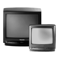
| Manufacturer | Panasonic |
| Model | TC-14RM10LP |
| Screen Size | 14 inches |
| Type | CRT |
| Input Ports | RF, Composite |
Details the controls and functions of the remote.
Procedure to reset the TV using front panel and remote controls.
Steps to access the TV's service mode for adjustments.
Adjustments available within the CHK1 service mode menu.
Details adjustments for Video Control adjustments in CHK2 mode.
Details adjustments for pincushion settings in CHK3 mode.
Details adjustments for white balance settings in CHK4 mode.
Lists the required equipment for performing adjustments.
Procedure for adjusting the RF Automatic Gain Control.
Confirms the output level of the VIF detector circuit.
Procedure to confirm audio circuit performance for buzzing noise.
Confirms anode and heater voltages for CRT components.
Adjusts the PAL color output signal parameters.
Calibrates the sub-tint for NTSC color signals.
Verifies the operation of the protection circuit.
Adjusts sub-brightness and sub-contrast levels.
Procedure to adjust the focus of the picture.
Calibrates color purity for accurate display.
Calibrates the white balance and quality of the picture.
Adjusts the convergence of color beams for a sharp image.
Calibrates the CRT cut-off levels for proper operation.
Calibrates vertical deflection parameters like slope and amplitude.
Final calibration of white balance in low and high light conditions.
Schematic diagram for the CRT Printed Circuit Board.