24
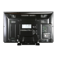
8.10. Remove the SS-Board
1. Remove the Tuner unit. (See section 8.5.)
2. Disconnect the connector (SS11).
3. Disconnect the flexible cable (SS33).
4. Disconnect the flexible cables (SS61 and SS66).
5. Remove the screws (×5 ) and remove the SS-Board.
8.11. Remove the Stand bracket
1. Remove the Plasma panel section from the servicing
stand and lay on a flat surface such as a table (covered
by a soft cloth) with the Plasma panel surface facing
downward.
2. Remove the AC inlet. (See section 8.2.)
3. Remove the Stand bracket fastening screws (×5 , ×4
) and the Stand bracket.
8.12. Remove the C1-Board
1. Remove the Stand bracket. (See section 8.11.)
2. Disconnect the flexible cables (CB1, CB2, CB3, CB4,
CB5, CB6 and CB7).
3. Disconnect the flexible cables (C10 and C11).
4. Disconnect the connector (C14).
5. Remove the screws (×4 ) and remove the C1-Board.
8.13. Remove the C2-Board
1. Remove the Stand bracket. (See section 8.11.)
2. Disconnect the flexible cables (CB8, CB9, CB10, CB11,
CB12, CB13, CB14 and CB15).
3. Disconnect the flexible cables (C20, C21 and C23).
4. Disconnect the connector (C25).
5. Remove the screws (×4 ) and remove the C2-Board.
8.14. Remove the Chassis support
metals and the M8 nut metals
1. Remove the Stand bracket. (See section 8.11.)
2. Remove the screws (×3 each) and remove the Chas-
sis support metal (L, R) and the M8 nut metal top (L, R).
3. Remove the screw (×1 each) and remove the M8 nut
metal bottom (L, R).

 Loading...