20
7.13. Remove the SS-Board
1. Remove the Tuner unit. (See section 7.4.)
2. Unlock the cable clampers to free the cable.
3. Disconnect the connectors (SS3, SS11 and SS23).
4. Disconnect the flexible cable (SS53A).
5. Disconnect the bridge connector (SS22-SS24).
6. Remove the screws (×5 ) and remove the SS-Board.
7.14. Remove the Hanger metals and
the Stand brackets
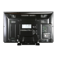
1. Remove the Plasma panel section from the servicing
stand and lay on a flat surface such as a table (covered)
with the Plasma panel surface facing downward.
2. Remove the Hanger metals (L, R) fastening screws (×4
each) and remove the Hanger metals (L, R).
3. Remove the Stand brackets (L, R) fastening screws (×4
each) and remove the Stand bracket metals (L, R)
and the Stand brackets (L, R).
7.15. Remove the C1-Board
1. Remove the Control button unit. (See section 7.7.)
2. Remove the Hanger metal R and the Stand bracket R.
(See section 7.14.)
3. Remove the flexible cables holder fastening screws (×8
).
4. Disconnect the flexible cables (CB1, CB2, CB3 and CB4).
5. Disconnect the connector (C14).
6. Disconnect the flexible cable (C10).
7. Remove the screws (×4 ) and remove the C1-Board.
7.16. Remove the C2-Board
1. Remove the Tuner unit. (See section 7.4.)
2. Remove the Hanger metal L and the Stand bracket L.
(See section 7.14.)
3. Remove the flexible cables holder fastening screws (×8
).
4. Disconnect the flexible cables (CB5, CB6, CB7 and CB8).
5. Disconnect the flexible cables (C20, C21 and C22).
6. Disconnect the connectors (C23 and C25).
7. Remove the screws (×4 ) and remove the C2-Board.

 Loading...


