Do you have a question about the Panasonic Technics SU-CH7 and is the answer not in the manual?
Detailed technical specifications for the SU-CH7 amplifier, including power output and input sensitivity.
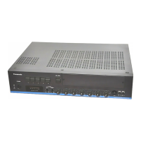
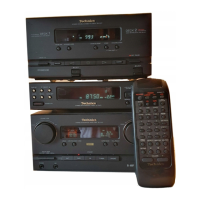
Lists the components that make up the SC-CH7 system, such as tuner, amplifier, and CD player.
Essential steps to take before starting any repair work, including power discharge and voltage checks.
Explains the role of the protection circuit and troubleshooting steps if it activates.
Lists the accessories supplied with the unit, such as power cords and antennas.
Illustrates how to install the system components vertically, horizontally, or in a line.
Instructions for connecting internal flat cables between amplifier, cassette deck, and CD player.
Guide on how to connect speaker cables, matching wire colors to terminals.
Details on connecting DAT decks and turntables using stereo pin cords.
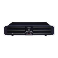
Identifies and explains the functions of the amplifier's front panel controls and indicators.
Details the various indicators and displays on the amplifier, including spectrum analysis and volume level.
Step-by-step guide for removing the outer cabinet, front panel, and related PCBs.
Instructions for disassembling and removing internal printed circuit boards like operation, rear panel, and input/output.
Details on removing power IC, transformer, fan motor, and AC inlet PCB during disassembly.
Procedure for checking the main PCB and removing the AC inlet PCB.
Explains the FL panel grid assignment, pin connections, and anode connections for display control.
Detailed circuit diagrams for the input/output terminal and main circuit sections.
Circuit diagrams for the amplifier, FL drive, and related circuits.
Circuit diagrams for power control, mic/headphones jack, and AC in circuits.
Detailed schematics for operation, control, and power circuits.
Detailed schematics covering power supply, audio, and AC input sections with notes.
Layout diagrams showing the component placement on input/output, main, and FL drive PCBs.
Layout diagrams for the volume/filter amplifier and AC inlet printed circuit boards.
Layout diagrams for operation, power control, and mic/headphones jack PCBs.
Detailed pin functions for IC601 (M5D945-083SP) and other ICs.
Diagram showing the overall wiring connections between different parts of the system.
Block diagram illustrating signal flow from input selector through mixing and phase shift stages.
Block diagram showing signal path through graphic equalizer, electric volume, and power amplifier stages.
List of integrated circuits and transistors with their part numbers and descriptions.
List of diodes, switches, and jacks with their part numbers and remarks.
List of connectors, fuse holders, and relays with their part numbers and remarks.
Detailed list of resistors, including part numbers, values, and remarks.
List of remaining resistors and initial capacitor part numbers and values.
Continues the list of capacitors with their part numbers, values, and remarks.
List of cabinet parts, accessories, and packing materials with their respective part numbers.
Diagrams illustrating the location of various cabinet parts and their assembly.
Illustrations and descriptions of how the system components are packed for shipping.
| Power Output | 30W + 30W (8Ω, 20Hz-20kHz, 0.08% THD) |
|---|---|
| Type | Integrated Amplifier |
| Frequency Response | 20Hz to 20kHz |
| Input Sensitivity | 2.5mV (MM), 150mV (line) |
| Signal to noise ratio | 76dB (MM) |