EasyManua.ls Logo

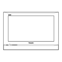
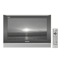
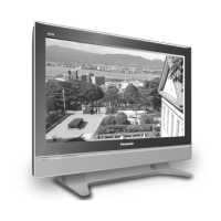
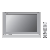
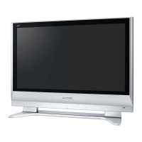
Panasonic TH-42PA60M

Panasonic TH-42PA60M
162 pages
To Next Page IconTo Next Page
Loading...
© 2006 Matsushita Electric Industrial Co., Ltd. All
rights reserved. Unauthorized copying and
distribution is a violation of law.
TH-37PA60H
TH-37PA60M
TH-42PA60A
TH-42PA60H
TH-42PA60M
TH-42PA60MT
GP9DE Chassis
Plasma Television
Specifications
Power Source AC 220-240 V, 50 / 60 Hz
Power Consumption
Average use 232 W (37-inch)
294 W (42-inch)
Standby condition 0.3 W
Plasma Display panel
Drive method AC type
Aspect Ratio 16:9
Contrast Ratio Max 10000:1
Visible screen size
(No. of pixels)
94 cmV (37-inch), 106 cmV (42-inch)
818 mm (W) × 461 mm (H) × 939 mm (diagonal) (37-inch)
920 mm (W) × 518 mm (H) × 1,056 mm (diagonal) (42-inch)
408,960 (852 (W) × 480 (H)) [2,556 × 480 dots]
Sound
Speaker 12 cm × 6 cm × 2 pcs, 8 W
Audio Output 20 W (10 W + 10 W ), 10% THD
Receiving Systems /
Band name (PA60A)
ORDER NO.ITD0603007CE

Table of Contents

Question and Answer IconNeed help?

Do you have a question about the Panasonic TH-42PA60M and is the answer not in the manual?

Panasonic TH-42PA60M Specifications

General IconGeneral
Screen Size42 inches
Display TypePlasma
Resolution1024 x 768
Aspect Ratio16:9
Contrast Ratio10000:1
HDMI Ports2
Component Video Inputs2
Viewing Angle160 degrees
Input PortsComposite, S-Video
Brightness1000 cd/m²

Summary

Specifications

Connection Terminals and Physical Details

Safety Precautions for Servicing

Touch-Current Check Procedure and Limits

Procedure and limits for checking touch currents to prevent shock hazards.

Electrostatic Discharge (ESD) Prevention

Service Information and Hints

Plasma Panel Replacement Procedures

Removing K-Board, Stand Brackets, and Plasma Panel

Step-by-step guide for safely separating the plasma panel from the front frame.

Installing New Plasma Panel

Final steps for installing a new plasma panel, including connecting cables and attaching components.

Self-Check and Troubleshooting Guides

Power LED Blinking Timing Chart

Table correlating power LED blink patterns with potential fault locations.

No Power Troubleshooting Flowchart

Troubleshooting flowchart for diagnosing 'No Power' issues.

No Picture Troubleshooting Flowchart

Troubleshooting flowchart for diagnosing 'No Picture' issues.

Local Screen Failure Diagnosis

Identifies potential PCBs responsible for local screen failures.

Service Mode Operations

Entering Service Mode 1 Procedure

Procedure to enter SERVICE 1 mode using sound menu and remote.

Entering Service Mode 2 Procedure

Procedure to enter SERVICE 2 mode using channel, EQ, and remote.

Service Mode Option Descriptions

TV Adjustment Procedures

Driver Section Voltage Adjustments

Procedure to adjust driver section voltages using a multimeter.

Initialization Pulse Adjustment

Procedure to adjust initialization pulse using an oscilloscope.

PCB Exchange and Quick Adjustments

Cautions and quick adjustments after replacing PCBs.

Picture Parameter Adjustments

PAL Panel White Balance Adjustment

Detailed steps for adjusting white balance for PAL signals.

HD White Balance Adjustment

Detailed steps for adjusting white balance for HD signals.

Sub Bright Adjustment Procedure

Procedure for adjusting sub-bright levels.

ABL Adjustment Procedure

Procedure for adjusting the Automatic Brightness Limiter.

Sub-Contrast Adjustment Procedures

Procedures for adjusting sub-contrast for AV, RF, and HD systems.

Hotel Mode Configuration

Schematic and Block Diagrams

Main Block Diagram

Overall block diagram of the TV system, showing major functional units.

P-Board Block Diagrams

Block diagrams illustrating the P-Board's functionality for different models.

P-Board Schematic Diagrams (37-inch)

Detailed schematics for P-Board sections 1 through 6 (37-inch).

P-Board Schematic Diagrams (42-inch)

Detailed schematics for P-Board sections 1 through 6 (42-inch).

PA-Board Block and Schematic Diagrams

Block and detailed schematics for the PA-Board.

H, K, and TA-Board Block Diagrams

Block diagrams illustrating the functions of H, K, and TA-Boards.

HC-Board Block Diagram

Block diagram illustrating the HC-Board's functions.

H-Board Schematic Diagrams

Detailed schematics for H-Board sections 1 through 3.

HC and TA-Board Schematic Diagram

Detailed schematic for HC and TA-Boards.

DG-Board Block Diagrams

Block diagrams illustrating the DG-Board's functions (parts 1-3).

DG-Board Schematic Diagrams

Detailed schematics for DG-Board sections 1 through 8.

Parts Lists

Related product manuals