EasyManua.ls Logo

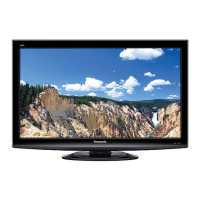
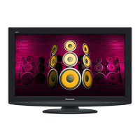
Panasonic TH-L32C10R2

Panasonic TH-L32C10R2
121 pages
To Next Page IconTo Next Page
Loading...
© Panasonic Corporation 2009. Unauthorized
copying and distribution is a violation of law
ORDER NO. MTV0901849CE
LCD TV
Model No. TH-L32C10R2
Chassis: KM02
Destination: IRAN
Specifications
Power Source AC SINGLE 220 - 240V, 50/60 Hz
Power Consumption
Average use 99 W
Standby condition 0.7 W
Display panel
Aspect Ratio 16:9
Visible screen size 80 cm (diagonal)
698 mm (W) × 392 mm (H)
Number of pixels 1,049,088 (1,366 (W) × 768 (H))
Sound
Speaker Full range × 2 pcs, 8 Ω
Audio Output 20 W (10 W + 10 W), 10% THD
PC Signals VGA, SVGA, XGA
SXGA ...... (compressed)
Horizontal scanning frequency 31 - 69 kHz
Vertical scanning frequency 59 - 86 Hz
Receiving Systems / Band name 17 SYSTEMS FUNCTIONS
1 PAL B, G, H
Reception of broadcast transmission and
playback from video cassette tape recorders.
2 PAL I
3 PAL D, K
4 SECAM B, G
5 SECAM D, K
6 SECAM K1
7 NTSC M (NTSC 3.58 / 4.5MHZ)
8 NTSC 4.43 / 5.5 MHz
Playback from special VCR’s or DVD.
9 NTSC 4.43 / 6.0 MHz
10 NTSC 4.43 / 6.5 MHz
11 NTSC 3.58 / 5.5 MHz
12 NTSC 3.58 / 6.0 MHz
13 NTSC 3.58 / 6.5 MHz
14 SECAM I

Table of Contents

Question and Answer IconNeed help?

Do you have a question about the Panasonic TH-L32C10R2 and is the answer not in the manual?

Panasonic TH-L32C10R2 Specifications

General IconGeneral
BrandPanasonic
ModelTH-L32C10R2
CategoryLCD TV
LanguageEnglish

Summary

Product Specifications

Power, Display, and Sound Details

Details on power source, consumption, panel specs, and audio.

Signal Reception and Connectivity

Supported TV systems, PC signals, and input/output terminals.

Physical Dimensions and Operating Conditions

TV size, weight, and environmental requirements.

Disassembly and Assembly Instructions

Chassis and Bracket Installation

Installing main chassis, AC cord, VESA, and AV brackets.

Component Installation Procedures

Steps for pedestal, LED/LCD panels, speakers, and control panel.

Back Cover and EMI Compliance

Back cover assembly, felt sticking, and EMI specs.

Service and Measurement Procedures

Service Modes and Adjustments

Self-check, hotel mode, voltage measurement, white balance.

Printed Circuit Board Identification

Parts location diagrams for the A-Board.

Schematic Diagrams and Parts List

Schematic Diagram Notes

Explains symbols and notes for schematic diagrams.

Exploded View and Replacement Parts

Visual breakdown and list of replacement parts.
Related product manuals