EasyManua.ls Logo

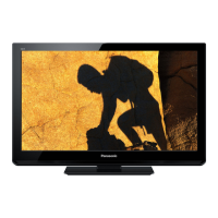
Panasonic TH-L32C3D

Panasonic TH-L32C3D
107 pages
To Next Page IconTo Next Page
Loading...
© Panasonic Corporation 2011. Unauthorized
copying and distribution is a violation of law.
ORDER NO. PAVCI1105019CE
LCD TV
Model No. TH-L32C3D
Chassis: KM10
Destination: INDIA
TABLE OF CONTENTS
PAGE PAGE
1 Safety Precautions----------------------------------------------- 3
1.1. General Guidelines---------------------------------------- 3
1.1.1. Leakage Current Cold Check---------------------- 3
1.1.2. Leakage Current Hot Check (See Figure
1.) --------------------------------------------------------- 3
2 Warning -------------------------------------------------------------- 4
2.1. Prevention of Electrostatic Discharge (ESD)
to Electrostatically Sensitive (ES) Devices---------- 4
2.2. About lead free solder (PbF)---------------------------- 5
3 Service Navigation ----------------------------------------------- 6
3.1. Service Hint ------------------------------------------------- 6
3.2. Applicable signals ----------------------------------------- 7
4 Specifications ----------------------------------------------------- 8
5 Service Mode -----------------------------------------------------10
5.1. How to enter into Service Mode ----------------------10
5.1.1. Contents of adjustment mode --------------------10
5.1.2. How to exit---------------------------------------------10
5.2. SRV-TOOL ------------------------------------------------- 11
5.2.1. How to access ----------------------------------------11
5.2.2. Display of SOS History ---------------------------- 11
5.2.3. POWER ON TIME/COUNT----------------------- 11
5.2.4. Exit ------------------------------------------------------ 11
5.2.5. Self Check Mode ------------------------------------ 12
5.2.6. Hotel Mode Adjustment---------------------------- 12
5.2.7. Hotel Mode-------------------------------------------- 12
6 Troubleshooting Guide --------------------------------------- 13
6.1. Check of the IIC bus lines------------------------------ 13
6.1.1. How to access --------------------------------------- 13
6.1.2. Exit ------------------------------------------------------ 13
6.1.3. Screen display --------------------------------------- 13
6.2. Power LED Blinking timing chart --------------------- 14
6.3. No Power--------------------------------------------------- 14
7 Disassembly and Assembly Instructions--------------- 15
7.1. AC Cord Dressing---------------------------------------- 15
7.2. AC Cord Installation ------------------------------------- 16
7.3. Control Panel Assembly-------------------------------- 17
7.4. Speaker Assembly --------------------------------------- 18
7.5. LCD Panel Fixing & Handling Method -------------- 19

Table of Contents

Question and Answer IconNeed help?

Do you have a question about the Panasonic TH-L32C3D and is the answer not in the manual?

Panasonic TH-L32C3D Specifications

General IconGeneral
Screen Size32 inches
Resolution1366 x 768
Display TypeLCD
BacklightCCFL
HDMI Ports2
USB Ports1
Aspect Ratio16:9
Response Time6.5 ms
VGA Port1
Component Video Input1
Composite Video Input1
Headphone Jack1
Standby Power Consumption0.3W
Speaker Output10W x 2
Audio Output20W (10W x 2)

Summary

Safety Precautions

General Safety Guidelines

General safety guidelines and leakage current checks for safe servicing.

Warnings and Precautions

ESD and Solder Handling

Prevent ESD damage and handle lead-free solder correctly for safety.

Service Navigation and Operations

Service Hints and Signals

Hints for service access and applicable input signal types.

Service Mode and SRV-TOOL

Procedures for entering, adjusting, and exiting service modes and using SRV-TOOL.

Troubleshooting and Diagnostics

Guides for checking IIC bus, LED timing, and diagnosing power issues.

Disassembly and Assembly

Internal Component Assembly

Instructions for assembling AC cord, control panel, and speaker units.

Panel and Cover Servicing

Procedures for handling LCD panels, LED panels, and back covers.

Stand Mounting Procedures

Steps for correctly mounting the TV stand.

Measurements and Adjustments

Voltage Charts and Picture Adjustment

Voltage charts for A/P boards and picture level adjustment procedure.

System Diagrams

Main Block Diagram

Overview of the TV's main functional blocks and signal flow.

Wiring Connection Diagram

Diagram showing wire dressing and connections to connectors.

Schematic Diagrams

Schematic Diagram Notes

General notes and symbols used in schematic diagrams.

A Board Schematics Overview

Detailed schematics for the A Board, covering various functional blocks.

Other Board Schematics (GK, KA, P)

Schematic diagrams for GK, KA, and P boards detailing their circuitry.

Printed Circuit Board Layouts

A-BOARD Layouts

Component placement diagrams for the A-board.

Other Board Layouts

Component placement diagrams for GK, KA, and P boards.

Replacement Parts Information

Mechanical Parts List

Exploded views and lists of mechanical replacement parts.

Electrical Parts List

Detailed list of electrical components and their part numbers.

Related product manuals