Do you have a question about the Panasonic TH-L32C10S and is the answer not in the manual?
Covers power source, consumption, and display panel characteristics.
Details on sound output, speaker specifications, and supported TV systems.
Explains various input and output connection terminals like AV, HDMI, PC.
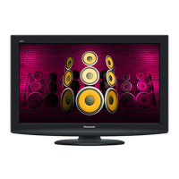
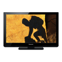
Specifies the TV's physical size and weight.
Procedures for installing the chassis and managing internal wiring.
Identifies the placement of controls and major components.
Essential safety practices for servicing the unit.
Steps for performing leakage current checks to ensure safety.
Illustrates the main components and connections within the KM02 chassis.
Techniques to prevent ESD damage to sensitive electronic components.
Details on PbF composition, properties, and handling precautions.
Explains how LED blinking patterns identify specific fault conditions.
Instructions for mounting the main chassis and associated brackets.
Provides guidance on routing and securing internal wires for optimal layout.
Step-by-step instructions for installing the AC power cord.
Guide for assembling the VESA mounting hardware.
Instructions for attaching VESA brackets to the rear panel.
Steps for assembling the TV stand and its base.
Procedure for installing the LED panel and connecting its wiring.
Guide for assembling the front control panel components.
Instructions for securing metal parts and the control panel assembly.
Details on applying felt to the side AV bracket for protection.
Steps for mounting and connecting the internal speakers.
Instructions for connecting the LVDS cable and other wires to the LCD panel.
Guide for attaching mounting brackets and VESA assemblies to the LCD panel.
Procedure for installing the LCD panel into the main cabinet.
Guidelines for routing LVDS wires to ensure proper EMI performance.
Instructions for applying felt to the back cover for insulation and vibration dampening.
Procedure for entering and exiting the unit's self-check diagnostic mode.
Steps to access and adjust settings for hotel mode operation.
Tables detailing expected voltage levels for key points on A and P boards.
Specifies desired values for white balance calibration.
Diagram showing component placement on the A-Board's front side.
Diagram showing component placement on the A-Board's back side.
Explains symbols, units, and conventions used in schematic diagrams.
First sheet of the A-Board schematic, detailing initial circuits.
Start of a major section of A-Board schematics covering various ICs.
Schematic detailing various I/O interfaces.
Schematic of the K Board, showing button inputs and related circuits.
First sheet of the P Board schematic, showing power supply circuits.
Schematic for the remote control and sensor input circuits.
Schematic showing power LED driver circuits.
Explains abbreviations and safety notices for component replacement.
List of replacement capacitors with part numbers and descriptions.
List of replacement diodes with part numbers and descriptions.
List of replacement ICs and coils with part numbers and descriptions.
List of replacement transistors and resistors with part numbers.
List of various other components like connectors, fuses, and relays.
Illustrates the location of major parts within the TV assembly.
Shows the steps for packing the TV for shipment.
Comprehensive list of all replaceable parts with part numbers and quantities.
| Display Type | LCD |
|---|---|
| Aspect Ratio | 16:9 |
| HDMI Ports | 2 |
| HD Technology | HD Ready |
| Component Video Input | 1 |
| Composite Video Input | 1 |
| Audio Output Power | 10W x 2 |
| Power Consumption | 110 W |
| Standby Power Consumption | 0.3 W |
| Screen Size | 32 inches |
| Resolution | 1366 x 768 |
| Viewing Angle | 178° (Horizontal & Vertical) |
| VGA Port | Yes |
| Headphone Jack | Yes |



 Loading...