© Panasonic Corporation 2014.
ORDER NO. MTV1401340CE
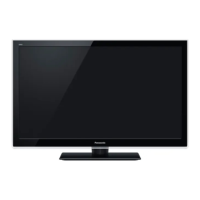
LED TV
Model No. TH-L32SV6K
Chassis: KM22
Destination: INDONESIA
TABLE OF CONTENTS
PAGE PAGE
1 Safety Precautions----------------------------------------------- 3
1.1. General Guidelines---------------------------------------- 3
1.1.1. Leakage Current Cold Check---------------------- 3
1.1.2. Leakage Current Hot Check (See Figure
1.) --------------------------------------------------------- 3
2 Warning-------------------------------------------------------------- 4
2.1. Prevention of Electrostatic Discharge (ESD)
to Electrostatically Sensitive (ES) Devices---------- 4
2.2. About lead free solder (PbF)---------------------------- 5
3 Service Navigation ----------------------------------------------- 6
3.1. Service Hint ------------------------------------------------- 6
4 Specifications ----------------------------------------------------- 7
5 Service Mode ------------------------------------------------------ 8
5.1. How to enter into Service Mode ----------------------- 8
5.1.1. Purpose ------------------------------------------------- 8
5.1.2. Contents of adjustment mode --------------------- 8
5.1.3. How to exit---------------------------------------------- 8
5.1.4. Display of SOS History ------------------------------ 8
5.1.5. POWER ON TIME/COUNT ------------------------ 8
5.1.6. Exit-------------------------------------------------------- 8
5.1.7. Self Check Mode --------------------------------------9
5.1.8. Hotel Mode Adjustment------------------------------9
5.1.9. Hotel Mode----------------------------------------------9
6 Troubleshooting Guide --------------------------------------- 10
6.1. Check of the IIC bus lines------------------------------ 10
6.1.1. How to access --------------------------------------- 10
6.1.2. Self-check indication only ------------------------- 10
6.1.3. Self-check indication and forced to factory
shipment setting ------------------------------------- 10
6.1.4. Exit ------------------------------------------------------ 10
6.2. Power LED Blinking timing chart --------------------- 11
6.3. No Power--------------------------------------------------- 11
7 Disassembly and Assembly Instructions--------------- 12
7.1. LED Panel and Bracket Ass’y------------------------- 12
7.2. LCD Panel Fixing & Handling Method -------------- 13
7.3. LCD Panel Assembly ----------------------------------- 14
7.4. Metal Bracket --------------------------------------------- 15
7.5. Control Panel Preparation ----------------------------- 16
7.6. PCB Installation ------------------------------------------ 17
7.7. Pedestal Ass’y -------------------------------------------- 18


 Loading...