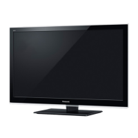
Do you have a question about the Panasonic TH-L42E3S and is the answer not in the manual?
Covers general safety rules for servicing equipment, including lead dress and protective devices.
Details procedures for cold and hot leakage current testing to prevent shock hazards.
Techniques to prevent component damage from static electricity when handling sensitive devices.
Guidelines for working with lead-free solder, including melting points and handling precautions.
Provides general tips and board identification for servicing the TV.
Describes the button sequence to access the service mode menu.
Details access and functions of the SRV-TOOL utility for diagnostics.
Covers purpose and settings for hotel mode functionality, restricting features.
Procedure to check IIC bus communication status via self-check.
Interprets power LED blinking codes for fault diagnosis.
Diagnostic flow for units that do not power on, checking power sources and fuses.
Shows how to secure the AC power cord during assembly using re-use bands.
Precautions for safely installing and handling the LCD panel to prevent damage.
Steps to assemble the main A and P boards onto the chassis.
Procedure for attaching the rear back cover using specified screws.
Specifies test points and voltage values for the A-board for verification.
Specifies test points and voltage values for the P-board for verification.
Shows the overall system architecture and component interconnections.
Illustrates cable routing and clamper usage for proper internal wiring.
Explains schematic symbols, measurement conditions, and safety remarks.
Schematic detailing IIC bus connections for various ICs.
Schematic of HDMI input and related circuitry.
Schematic of video and audio input/output circuits.
Schematic for USB, Ethernet, and PC interfaces.
Schematic for memory interfaces and JTAG.
Schematic for Ethernet PHY and SD card interface.
Schematics for DC-DC converters.
Schematic of various power supply rails and voltage regulators.
Schematics for specific voltage regulators.
Schematics for DCDC converters.
Schematic of the DDR3 memory interface.
Schematic of the remote receiver and sensor circuits.
Schematic for the power LED indicator circuit.
Schematic of the AC input and initial power supply stages.
Schematic of power control ICs and associated components.
Schematic of voltage regulators and power output stages.
Top-side component placement diagram for the A-Board.
Bottom-side component placement diagram for the A-Board.
Component placement diagrams for the KA-Board.
Top-side component placement diagram for the P-Board.
Lists mechanical parts for exploded view references.
Notes on component abbreviations and retention time.
Detailed list of replacement capacitors with part numbers.
List of replacement diodes, ICs, and coils.


 Loading...