'I
MPORT
ANT
SAFETY NOTICE
1
There are special components used
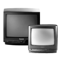
in
Panasonic
TV
sets which are important for safety. These parts are
id
entified
on the schematic diagram and on the replacement parts list.
It
is
essential that these critical parts should be
replaced with manufacturer's specified parts
to
pre
ven
t X-RAD
IA
TION, shock, f
ir
e, or o
ther
hazards.
Do
not
modify
the
original design_
without permission of
Matsushita
Electric.
The electrical parts used
in
this model-such as the resistors, t
he
ca
pacitors
and
the transistors, are smaller than the same
parts used
in
conventional models. Very painstaking
an
d care
ful
servicing tech
ni
que
s,
ther
efore, are
ne
cessary for this
model.
-----
DISASSEMBLY
INSTRUCTIONS-----
UPPE
R
CA
BIN
ET REMO
VAL
1.
Remove 4 screws
®
as
shown in Fig.
1.
2.
Lift
the
Rod
antenna.
®
HOW TO
1 .
Remove
2.
Remove
3.
Remove
Fig. 1
O
PE
N
THE P.C.B
OARD
the
the
the
upper cabinet.
P.C.Board bl
ock.
10P
socket
as
shown
in
10P
Socket
(Remove
the
solder)
®
Fig. 3.
P.C.BOARD
BLOCK
REMOVAL
1. Remove
the
side plate.
2.
Lift
the
escutcheon,
then
lift
the
under P.C.Board
with
flat
screw
driver
as
shown
in Fig
2.
Flat
Si
de
plat
e
U
nder
P.
C.
B
oar
d
Fig.
2
HOW
TO INSTALL
THE
SET
LEG
T
~
Se
t
leg
bcacket
B
~
I
'
Set
l
eg
-3
-
--
1
TR-1030P
-------FIELD
ALIGNME
NT--------
AVR
(AUTOMATIC
VOLTAGE
REGULATOR)
Connect
a
voltmeter
across B+
I ine and chassis.
Make
cer-
tain
the
B+
supply voltage
is
+4.SV
±
0.
05V.
Adjust
the
AVR
control
(VR71)
if
necessary.
YOKE
POSITION
The
yoke
is
secured
to
the
neck
of
the
picture
tube
with
an
angu lar
clamp
and screw.
To
Adjust
the
yoke
and
correct
for
picture
ti
lt : Loosen
the
clamp
screw,
correct
tilt,
and
retighten
the
clamp
screw.
CENTERING
The
picture
centering
device
co
nsists
of
two
rings
located
at
the
rear
of
the
yoke
assembly.
Ea
ch ring has a
tab
for
ease
of
adjustment.
The
tabs
should
be
rotated
and moved
towards
or
away
from
each
other
until
the
picture
is
properly
centered on
the
picture
tube
screen.
TO
ADJUST
THE AGC PROPERLY
(1)
Set the
channel selector
to
a
station
transmitting
a
strong
signal.
(2)
T
urn
the
RF
AGC
control
(VR1 9)
clockwise
or
coun-
terclockwise
to
the
point
where
the
snow
noise
dis-
appears in
the
picture.
(3)
Check
the
reception
on
al l channels.
V
ERTICAL
HEIGHT
Ad
just
the
V-Height
contro
l
(VR32)
until
picture
becomes
symmetrical
from
top
to
bottom.
VR19
RF
AGC
VR32
VR41 VR31
VR71
HEIGHT
H.HOLD
V.HOLD
AVR
Fig.5
INDICATOR
ALIGNMENT
------
Adjust
as follows
VR93
VR96
VR94
VR95
Steps
Rec
ei
vi
ng
Chann
el
U/V
Select
Co
nt
rol
Re
mark
1
low
es
t
~
VR92
UHF
2
hi
ghest
VR93
ADjust
each
3
low
band
VHF
VR96
control
to
(CH2-6)
get
the
best
picture.
low
est
of
4
hi
gh band
~
VR94
(CH7-
13
)
5
highest
of
-
VR95
hig h band
Bt
Boltage
Cha
nn
el
2 3
4
5 6
II
7 8
9
10
I
11
I
12
I
13
I
v
1.5
3.3
6
.1
1
3.5
23
.4
9.2
10.
6
11.9
13
.1
I
15
.1
I
17.7
I
22.1
I
Channel
14
20 30
40
50
60
70
83
u
1.9
3.4
6.7
9.3
11.4
14.1
17.3
25
-
4-
 Loading...