EasyManua.ls Logo

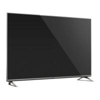
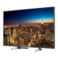
Panasonic TX-40DS500B User Manual

Panasonic TX-40DS500B
74 pages
To Next Page IconTo Next Page
Page #1 background imageLoading...
Page #1 background image
Service Manual
LED TV
TX-40DS500B
KM29E Chassis
© Panasonic Corporation 2016.
Unauthorized copying
and
distribution is a violation of law.
ORDER No. PCZ1602022CE
There are special components used in this equipment which are important for safety. These parts are marked in the
Schematic Diagrams, Circuit Board Diagrams, Explorer Views and Replacement Parts List. It is essentia l that th ese
critical parts should be replaced with manufacturer´s specified parts to p revent shock, fire or oth er hazards. Do not
modify the original design without permission of manufacturer.
IMPORTANT SAFETY NOTICE
This service information is designed for experienced repair technicians only and is not designed for use by the general public. It does not
contain warnings or cautions to advise non-technical individuals of potencial dangers in attempting to service a product. Products
powered by electricity should be serviced or repaired only by experienced professional technicians. Any attempt to service or repair the
product or products deal within this service information by anyone else could result in serious injury or death.
Warning
Question and Answer IconNeed help?

Do you have a question about the Panasonic TX-40DS500B and is the answer not in the manual?

Panasonic TX-40DS500B Specifications

General IconGeneral
Screen Size40 inches
Resolution1920 x 1080 pixels
Display TypeLED
Smart TVYes
HDMI Ports3
USB Ports2
Audio Output20W
Wi-FiYes
EthernetYes
Backlight TechnologyDirect LED
Refresh Rate50 Hz
VESA Mount CompatibleYes
Energy Efficiency ClassA+

Summary

Safety Precautions

General Guide Lines

General guidelines for servicing the TV, emphasizing safety and proper installation of protective devices.

Touch-Current Check Procedure

Detailed steps for measuring touch current to prevent electric shock hazards after servicing.

Prevention of Electrostatic Discharge (ESD)

ESD Handling Techniques

Essential techniques to minimize component damage caused by electrostatic discharge (ESD).

Lead Free Solder Information

Suggested Pb Free Solder Types

Recommendations for lead-free solder types suitable for use in TV manufacturing and repair.

Service Navigation

Chassis Board Layout

Diagram illustrating the location and function of main circuit boards (A-Board, P-Board, K-Board).

Service Hints

How to Remove Pedestal Assembly

Step-by-step instructions for safely removing the TV's pedestal assembly.

How to Remove Backcover

Procedure for safely removing the TV's backcover for internal access.

Applicable Signals

Product Specifications

Technical Description

KEY Specification for Features

Details on feature keys (DTCP-IP, HDCP2, Netflix, etc.) and their generation process.

Replacement of ICs Procedure

Guidelines for replacing critical ICs like sLD8A and NAND FLASH, including SELF CHECK.

Model and Key Information

Table mapping TV models to supported features and their corresponding keys.

Setting Inspection

Voltage Confirmation Tests

Test points and expected voltage values for A-board and P-board for setting verification.

Service Mode Function

Entering Service Mode

Instructions on how to access the TV's service mode using the remote control.

Exiting Service Mode

Procedure for safely exiting the TV's service mode.

Service Tool Mode Operation

Accessing Service Tool Mode

Steps to enter the Service Tool Mode from the main Service Mode menu.

SOS History Display

Explanation of the SOS History display, indicating LED blinking patterns for error codes.

Power ON Time and On/Off Display

Information on viewing cumulative power ON time and switching counts.

Exit Service Tool Mode

Instructions on how to exit the Service Tool Mode.

Hotel Mode Configuration

Hotel Mode Purpose

Explanation of the Hotel Mode function, used to restrict TV features in hotel environments.

Hotel Mode Access Command

Command sequence required to enter the Hotel Mode setup menu.

Hotel Mode Setup Menu Details

Description of items and functions available within the Hotel Mode setup menu.

Data Copy Functions

USB Data Copy for Board Replacement

Procedure for copying setting data to USB for A-board replacement.

USB Data Copy for Hotel Installation

Procedure for copying setting data to USB for mass hotel installations.

USB Memory Preparation

Steps to prepare a USB memory stick with the correct startup file for data copy.

TV to USB Data Copy Procedure

USB to TV Data Copy Procedure

Option Bytes Description

OPTION1 Bytes Description

Description of option byte settings for OPTION1, controlling various TV functions.

OPTION2 Bytes Description

Description of option byte settings for OPTION2, related to sound and broadcast systems.

OPTION3 Bytes Description

Description of option byte settings for OPTION3, covering features like NICAM and SSU search.

OPTION4 Bytes Description

Description of option byte settings for OPTION4, including noise reduction and CAM workarounds.

OPTION16 Bytes Description

Description of option byte settings for OPTION16, related to PIP and sound menu features.

Self Check Procedures

Accessing Self Check Function

Instructions for accessing the self-check feature for diagnosing TV issues.

Exiting Self Check Function

Method to exit the self-check diagnostic mode.

Power LED Blinking Timing Chart

LCD Panel Test Mode

LCD Panel Test Mode Purpose

Objective of the LCD Panel Test Mode for identifying failure points.

Entering LCD Panel Test Mode

Instructions on how to activate the LCD Panel Test Mode.

Exiting LCD Panel Test Mode

Procedure to exit the LCD Panel Test Mode.

Confirming LCD Panel Test Results

Method for judging failure points based on test patterns displayed.

LCD Panel Test Mode Remarks

Important notes regarding the LCD Panel Test Mode and its test pattern generation.

Wiring Diagram

Block Diagram (1/2)

Block Diagram (2/2)

Parts Location Overview

Location of Lead Wiring

Location of Heat Rubbers

Location of Gaskets

Packing Structure Illustration

Replacement Parts List Notes

Parts List

Schematic Diagrams Note

A-BOARD (1/12) Schematic Diagram

A-BOARD (2/12) Schematic Diagram

A-BOARD (3/12) Schematic Diagram

A-BOARD (4/12) Schematic Diagram

A-BOARD (5/12) Schematic Diagram

A-BOARD (6/12) Schematic Diagram

A-BOARD (7/12) Schematic Diagram

A-BOARD (8/12) Schematic Diagram

A-BOARD (9/12) Schematic Diagram

A-BOARD (10/12) Schematic Diagram

A-BOARD (11/12) Schematic Diagram

A-BOARD (12/12) Schematic Diagram

P-BOARD (1/3) Schematic Diagram

P-BOARD (2/3) Schematic Diagram

P-BOARD (3/3) Schematic Diagram

K-BOARD Schematic Diagram

A-BOARD - TOP Conductor View

A-BOARD - BOTTOM Conductor View

P-BOARD - TOP Conductor View

P-BOARD - BOTTOM Conductor View

K-BOARD - TOP Conductor View

K-BOARD - BOTTOM Conductor View

Related product manuals