7-7
7
2WAY SYSTEM
Test Run
4. Auto Address Setting
Name And Function Of Each Switch On Outdoor Unit Control P.C. Board
Function Switch Remarks
MODE pin (3P, BLK)
(CN40)
Changes to cooling/heating mode. (Outdoor main unit is only usable.)
When in normal operation:
When short circuited the COOL side, indoor unit operation in the same
refrigerant system changes to all cooling mode.
When short circuited the HEAT side, indoor unit operation in the same
refrigerant system changes to all heating mode.
When in auto address setting: Changes to heating mode with open-circuit.
A.ADD pin (2P, WHT)
(CN30)
Short circuited for over 1 second long Auto address setting starts with open-circuit.
If short circuit lasts for over 1 second long during auto address setting, the setting is interrupted.
CHK pin (2P, WHT)
(CN23)
When short circuited, test run begins.
(If the remote controller is connected in test run mode, it is automatically cancelled after 1 hour.)
Also, if short-circuit is cancelled, test run mode is cancelled.
RC plug (3P, BLU)
(CN73)
Connects to outdoor unit maintenance remote controller and content of alarm message will be checked.
RUN pin (2P, WHT)
(CN27)
When short circuited and pulse signal is given, all indoor units operate in the same refrigerant system.
STOP pin (2P, WHT)
(CN28)
When short circuited and pulse signal is given, all indoor units stop in the same refrigerant system.
(When short circuited, operation cannot be performed by the indoor unit's remote controller.)
DEF pin (2P, WHT)
(CN25)
When the pin of the main unit is short-circuit in heating mode, defrosting operation is started.
* Even if short circuited, defrosting will not be activated immediately.
AP pin (2P, WHT)
(CN24)
Can be used when vacuuming the outdoor unit.
SNOW plug (3P, RED)
(CN34)
Can be used when installing a snowfall sensor device.
SILENT plug (2P, WHT)
(CN33)
Can be used when setting the outdoor unit fan in sound absorbing mode.
OC EMG terminal
(3P, BLK) (CN69)
If “TO INDOOR UNIT” accidently connected to high voltage, use the terminal base TM1.
Method: 1. Replace the pins 1 and 2 of CN69 with the pins 2 and 3.
2. Disconnect JP11.
RC1 EMG terminal
(3P, BLK) (CN82)
If “TO OUTDOOR UNIT” accidently connected to high voltage, use the terminal base TM1.
Method:
1. Replace the pins 1 and 2 of CN82 with the pins 2 and 3.
2. Disconnect JP12.
CN30
CN82
CN69
SW7
JP11
TM1
CN40
CN22
CN27
CN73
CN67
CN23 CN24
CN25
LED1
LED2
CN33 CN34
SW4
SW3
SW2
SW1
SW5
SW6
CN28
JP12
00_271537_2WAY_Eng.indb 49 2015-9-10 16:15:39
Case 1
Auto Address Control from Outdoor Unit
1. Regarding the number of outdoor units, set the Dip switch (SW6) for setting the number of outdoor units on Unit 1 control P.C.B to 3
units
ON
ON
OFF
and the Unit Number Setting Dip switch (SW5) to unit number 1.
ON
This unit becomes the outdoor main unit.
2. Set the Unit Number Setting switch (SW5) on unit 2 control P.C. board to unit number 2.
3
2
1
ON
Set the Unit Number Setting switch (SW5) on unit 3 control P.C. board to unit number 3.
3
2
1
ON
3. Check the refrigerant system's Address Setting Rotary switch (SW1) on outdoor main unit control P.C. board to “1”
and the Dip switch
(SW2) to “0” (at shipment).
ON
ON
OFF
4. Regarding the setting of the number of indoor units connected to the outdoor unit, set the Dip switch (SW4) for setting the number of
indoor units on outdoor main unit control P.C. board connected to the outdoor unit to “1”.
2
3
1
ON
ON
OFF
If the Rotary switch (SW3) set to “0”, 10 units can be prepared for operation.
5. Turn on power to indoor and outdoor units.
6. Short circuit the A.ADD pin (CN30) on outdoor main unit control P.C. board for over 1 second long and open circuit.
Communication for auto address setting begins.
* To cancel, short circuit the A.ADD pin (CN30) again for over 1 second long and then open circuit. The LED that
indicates auto address setting goes out and the process is stopped.
Be sure to perform auto address setting again.
Auto address setting is completed when LEDs 1 and 2 on outdoor main unit control P.C. board go out.
7. Remote control operation is now available.
* When auto address setting is controlled by the remote controller, perform auto address setting by the remote controller after step 5
described above.
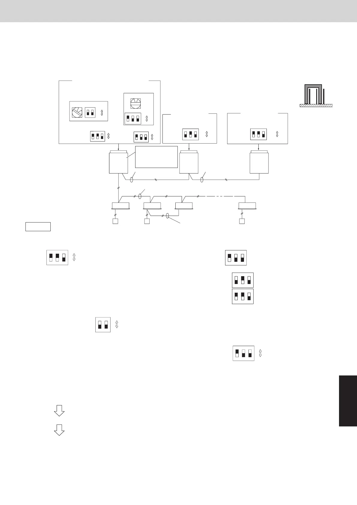
4. Auto Address Setting
Example: Basic Wiring Diagram (1)
• Case of no link wiring
(Inter-unit control wiring is not connected to a multiple system.)
Indoor unit address setting is possible without starting the compressor.
1
2
3
3
2
1
1
3
2
1
2
2
1
3
3
2
1
0
1
1-1 1-2 1-3 1-10
Unit 1 setting (outdoor main unit)
Unit 2 setting Unit 3 setting
3P terminating
resistance pin
(SHORT side)
No. of indoor units
(10 units setting)
System address
(System 1 setting)
(SW1)
(SW3)
(SW4)
(SW5)
(SW5) (SW5)
Unit 3
(Sub)
Inter-outdoor unit
control wiring
Remote control
communication wiring
Inter-unit control wiring
Outdoor Unit
Indoor unit
Remote controller
Set the terminating
resistance pin
to SHORT side.
(CN67)
Inter-outdoor unit
control wiring
Unit 2
(Sub)
Unit 1
(Main)
OPENSHORT
(SW6)
(SW2)
ON
ON
ON
ON
ON
ON
ON
ON
ON
ON
ON
ON
OFF
OFF
OFF
OFF OFF
OFF
Unit
number
setting
(unit 1)
Unit
number
setting
(unit 2)
Unit
number
setting
(unit 3)
Number
of outdoor
units (3 units
setting)
* It is not necessary to control the terminating
resistance pin (3P) (CN67) on the outdoor
unit P.C. board.
3P pin is plugged in SHORT side at shipment.
Confirm it is plugged in SHORT side.
00_271537_2WAY_Eng.indb 50 2015-9-10 16:15:40
SM830253-00_欧州2way7_SM-TRSM.indb 7 16/08/03 14:14:24
 Loading...