I - 2
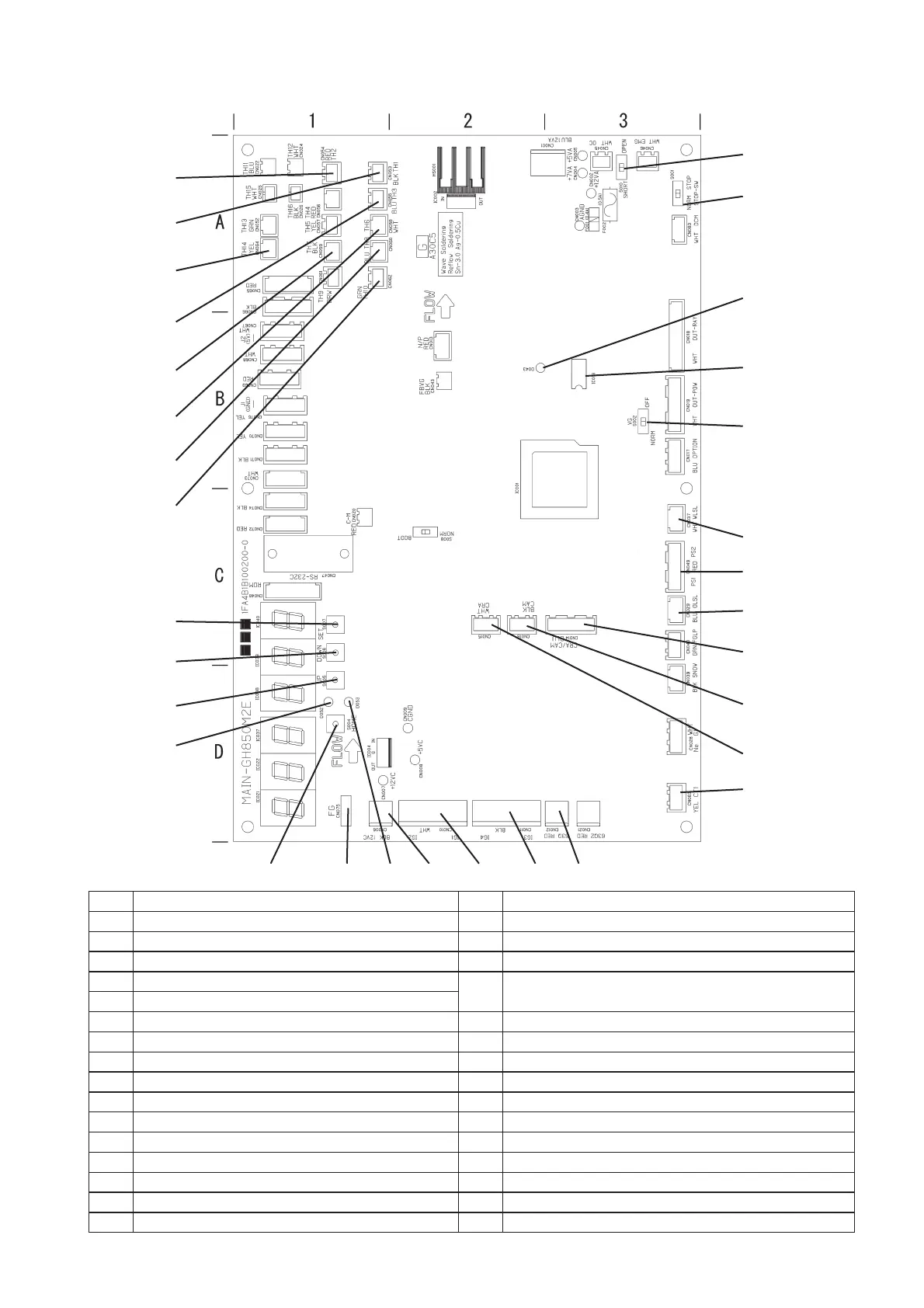
(3) Outdoor main board switch and LED arrangement diagram
No. Name No. Name
1 Terminating resistance ON/OFF switch (S010) 17 CN075
2 STOP SW (S001) 18 EEPROM
3 Indoor/outdoor communication monitor (D043) 19 CN037 (white)
4 Fuel gas solenoid valve force close switch (S002)
20
CN049 (red) Compressor outlet/inlet pressure sensors
PS1: Inlet, PS2: outlet
5 SET key (S007)
6 DOWN key (S006) 21 CN029 (blue)
7 UP key (S005) 22 CN014 (blue)
8 LEVEL LED (D053) 23 CN016 (black)
9 TEST/WARNING LED (D052) 24 CN062 (green) Hot water outlet temperature
10 HOME key (S004) 25 CN060 (blue) Clutch coil temperature
11 CN015 (white) 26 CN058 (white) Coolant temperature
12 CN063 (yellow) 27 CN059 (black) Outdoor air temperature
13 CN012 (red) 28 CN055 (blue) Heat exchanger inlet temperature
14 CN011 (black) 29 CN064 (yellow) Clutch 2 coil temperature
15 CN010 (white) 30 CN053 (black) Compressor inlet temperature
16 CN006 (black) 31 CN054 (red) Compressor outlet temperature
31
20
81710
9
7
6
5
24
25
26
27
28
29
30
19
4
18
3
2
1
13141516
23
22
21
12
11
M2PeriodicWmulti.indb2 2012/04/2014:46:27
 Loading...