Do you have a question about the Panasonic U-26PE1U6 and is the answer not in the manual?
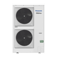
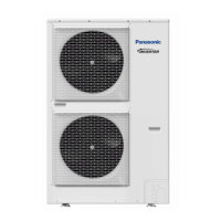
Detailed specifications for various indoor and outdoor unit models, including capacities, electrical ratings, and dimensions.
Specifications for key indoor unit components like fan motor, heat exchanger, and drain pump.
Specifications for outdoor unit components like thermistors, solenoid coils, and expansion valves.
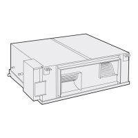
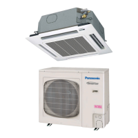
Physical dimensions and installation space requirements for various indoor and outdoor unit types.
Diagrams illustrating the refrigerant flow path for different outdoor and indoor unit configurations.
Specifies the operational temperature limits for indoor and outdoor air intake during cooling and heating.
Graphs showing capacity correction ratios based on indoor and outdoor temperature conditions.
Graphs indicating sound pressure levels for different indoor unit types across various frequencies.
Procedure to increase fan speed to address low airflow due to high external static pressure.
Methods for setting external static pressure for concealed duct units to ensure rated airflow.
Charts showing air throw distances based on fan speed, flap angle, and room temperature.
General precautions and recommended wire sizes for power supply and control wiring.
Guidelines for tubing size, density limits, and selecting/installing outdoor and indoor units.
Explanation of how the unit adjusts room temperature by controlling compressor ON/OFF cycles based on thermostat settings.
Controls indoor fan speed to prevent cold air drafts before heat exchange coils warm up during heating.
Describes how indoor fan speed is automatically adjusted based on room temperature for cooling and heating.
Details various control functions including electronic valve control, discharge temp release, and compressor protection.
Layout diagram and explanation of the functions of the outdoor unit control PCB (CR-CH4872R).
Explanation of the functions and switches on the outdoor unit control PCB (CR-CH4272R).
Electrical data including wiring diagrams and component symbols for various indoor unit types.
Electrical data including wiring diagrams and component symbols for various outdoor unit models.
Lists possible malfunctions and their corresponding alarm display codes for remote and receiver units.
Troubleshooting guide correlating remote controller alarm displays with potential causes and inspection points.
Detailed troubleshooting flowcharts for specific alarm codes like P03, P04, P05, P15, etc.
Resistance values of various temperature sensors (TO, TS, C1, C2, TD) at different temperatures.
Introduction to the outdoor unit maintenance remote controller and its purpose for EEPROM settings and monitoring.
Outlines the capabilities of the remote controller, including start/stop, mode switching, test runs, and display functions.
Details how to connect and operate the remote controller for normal display functions like system status and mode switching.
Procedure to display indoor and outdoor unit sensor temperatures using the remote controller.
Steps to view the outdoor unit's alarm history, including clearing the history.
Instructions for accessing and modifying EEPROM settings using Setting Mode 1.
Introduction to the CZ-RTC4 outdoor unit maintenance remote controller and its functions.
Lists the functions available on the ordinary display of the CZ-RTC4, including monitoring and mode settings.
Instructions for connecting and operating the CZ-RTC4 remote controller for normal display functions.
Procedure to display sensor temperatures for selected indoor or outdoor units using the CZ-RTC4.
Steps to view and clear the outdoor unit's alarm history using the CZ-RTC4.
Instructions for setting outdoor unit EEPROM parameters using Setting Mode 1 on the CZ-RTC4.
Essential checks and procedures before initiating the test run, including power supply and valve checks.
Important notes and cautions regarding unit combinations and test run procedures, especially with wired remote controllers.
Step-by-step instructions for performing the test run using wired remote controllers (CZ-RTC2, CZ-RTC3/CZ-RTC5, CZ-RTC4).
A checklist of essential items to verify before starting the test run, including crankcase heater and service valves.
Detailed procedures for initiating and managing test runs using different remote controller models (CZ-RTC2, CZ-RTC3/CZ-RTC5, CZ-RTC4).
Critical precautions for test runs, including customer presence, wiring checks, and handling of electrical components.
A table mapping remote controller alarm displays to causes and corrections for various unit types.
Illustrative wiring diagrams for single-type systems and group control configurations.
| Refrigerant | R410A |
|---|---|
| EER (Cooling) | 11.5 |
| Cooling Capacity | 26000 BTU/h |
| SEER | 16 |
| HSPF | 9.0 |
| Voltage | 208/230 V |
| Operating Temperature (Heating) | 5°F ~ 75°F |