5
5 - 3
3WAY SYSTEM
Trouble Diagnosis
1. Contents of Remote Controller
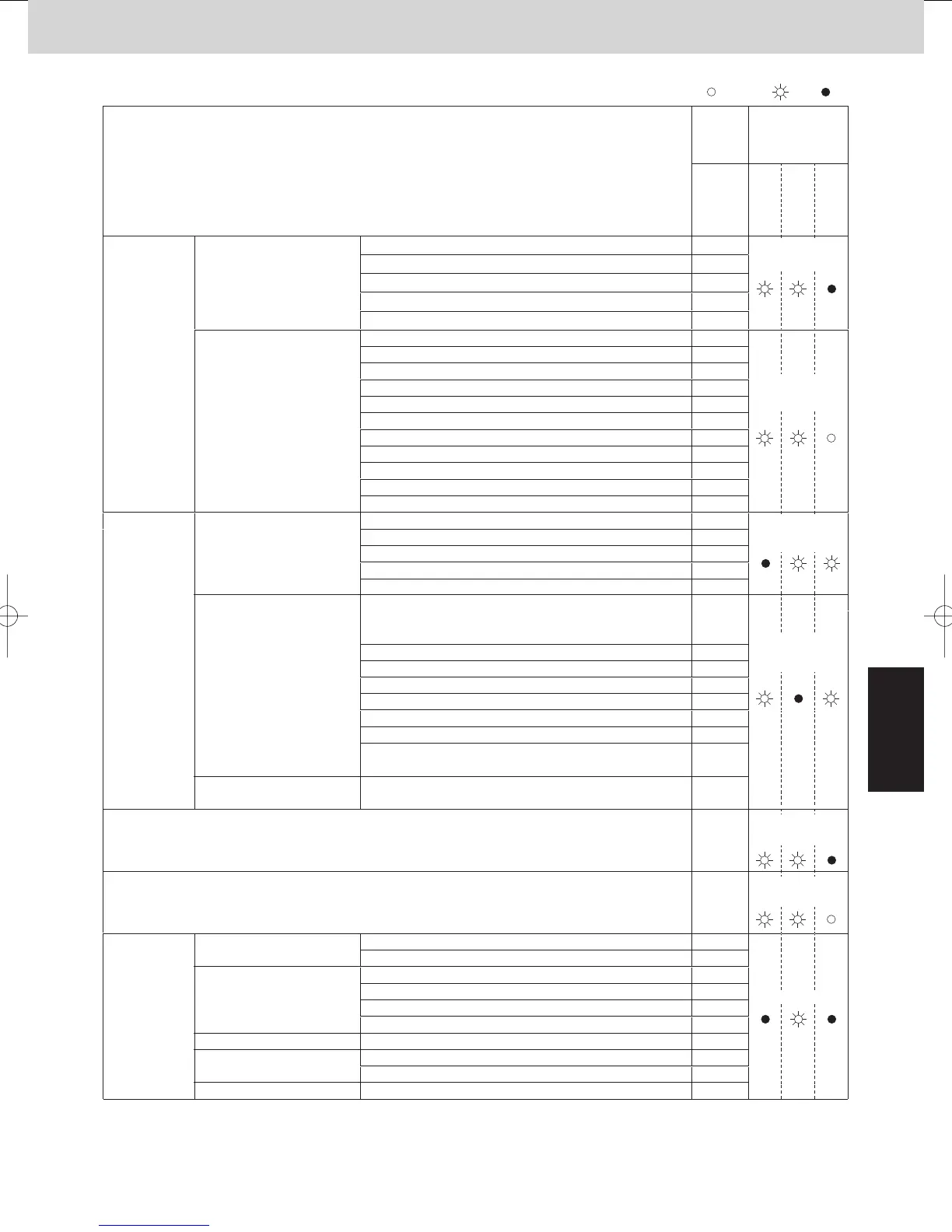
Switch Alarm Display
ON: Blinking: OFF:
Possible cause of malfunction
Wired
remote
control
display
Wireless
remote controller
receiver display
Operation
Timer
Standby
for heating
Outdoor thermistor is either
open or damaged.
Comp. No. 1 discharge gas temp. sensor (DISCH1)
Comp. No. 2 discharge gas temp. sensor (DISCH2)
Outdoor No. 1 coil gas temp. sensor (EXG1)
Outdoor No. 1 coil liquid temp. sensor (EXL1)
Outdoor air temp. sensor (AIR TEMP)
Compressor intake temperature sensor (SCT)
Temp. sensor at refrigerant gas outlet of dual-tube (SCG)
High pressure sensor failure. High pressure trouble.
Low-pressure sensor failure
Outdoor No. 2 coil gas temp. sensor (EXG2)
Outdoor No. 2 coil liquid temp. sensor (EXL2)
F04
F05
F06
F07
F08
F12
F14
F16
P12
F17
F23
F24
Improper wiring connections of ceiling panel. <<P09>>
<<P01>>
<<P10>>
Activation of
protective
device
Protective device in indoor
unit is activated.
Thermal protector in indoor unit fan motor is activated.
Float switch is activated.
Operation of protective function of fan inverter.
P31
When alarm message in other indoor units occurs in case of
group control, unalarmed state of indoor units are inoperative.
O2 sensor (detects low oxygen level) activated P14
< > alarm indication: In some cases may affect the operation of other indoor units.
Operating and timer
lamps blinking
altemately
Timer and heat
ready lamp blinking
altemately
Indoor thermistor is either
open or damaged.
Indoor coil temp. sensor (E1)
Indoor coil temp. sensor (E2)
Indoor coil temp. sensor (E3)
Indoor suction air (room) temp. sensor (TA)
Indoor discharge air temp. sensor (BL)
Thermistor fault
<<F01>>
<<F02>>
<<F03>>
<<F10>>
<<F11>>
Operating and
timer lamps blinking
alternately
P03
P04
P02
Protective device in outdoor
unit is activated.
Indoor unit communication
error of group control wiring.
Abnormal device function
Incorrect discharge temperature. (Comp. No. 1)
Compressor thermal protector is activated. Power supply
voltage is unusual. (The voltage is more than 260 V or less
than 160 V between L and N phase.)
High pressure switch is activated.
P05Negative (defective) phase.
<< >> alarm indication: Does not affect the operation of other indoor units.
Operating and heat
ready lamp blinking
altemately
P16
P17
DCCT overcurrent
Incorrect discharge temperature. (Comp. No. 2)
P22Outdoor unit fan motor is unusual.
Inverter for compressor is unusual.
(DC compressor does not operate.)
P29
H31IPM trip (IPM current or temperature)
EEPROM on indoor unit PCB failure
F29
EEPROM on the main or sub outdoor unit PCB has failed.
F31
Protective
device
for compressor
is activated
Protective device for
compressor No. 1 is activated.
Operating and timer
lamp blinking
simultaneously
Operating and timer
lamp blinking
simultaneously
Protective device for
compressor No. 2 is activated.
H12
H11
Compressor No. 2 current trouble (locked)
Compressor No. 2 CT sensor disconnected or short circuit
Compressor No. 2 discharge temp. sensor disconnected
Low pressure switch is activated.
Comp. No. 1 oil sensor
H13
Oil sensor fault.
(Disconnection, etc.)
H15
Comp. No. 2 oil sensor
H06
H08
H27
Timer lamp blinking
H03Current is not detected when comp. No. 1 is ON.
H01Compressor No. 1 current trouble (overcurrent)
Compressor No. 2 current trouble (overcurrent)
5/A9#;'%1K5;56'/A5G
 Loading...