Installation Guide
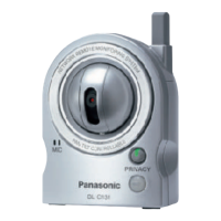
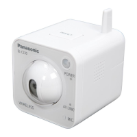
Wireless Sensor Camera
Model No.
VL-WD812EX
(Wireless sensor camera
is described as "camera"
in this guide.)
Note to the installer
■
Please read this guide carefully, and install the product safely and correctly by following the
instructions. Carefully read the information found in the section titled "For your safety" in
particular.
■
Only use attachments/accessories specied by the manufacturer.
■
The installation shall be carried out in accordance with all applicable installation rules.
■
Panasonic assumes no responsibility for injuries or property damage resulting from failures
arising out of improper installation or operation inconsistent with this guide. Additionally, any
resulting malfunction will not be covered under the warranty.
■ After installation, make sure to leave this
guide
with the customer.
Supplied accessories for installation
□
Cap removement tool x 1
□
Power supply unit x 1
□
Screw cover x 4
□
Cable binder x 2
□
Washer x 1
□
Wall mount bracket x 1
□
Screw x 4
□
Sensor range cap
x 1 set of 4
Used to attach the
wall mount bracket
to the camera
Used to remove the
sensor range caps
from the camera
Used when
attaching the safety
wire to the wall
Power supply unit and related items
Used for the heat
sensor
(4 mm × 20 mm)
4 mm
Important:
● You will need the following additional items to install and congure the camera.
[Locally procured]
– Screws (for wall mount bracket: × 4, for safety wire: × 1):
Prepare the screws (
the drawing on the right) according to the
material, structure, strength and other factors of the mounting area
and the total weight of objects to be mounted.
– Power cables (AC/DC cables), wires (for an external sensor connection):
Prepare cables and wires of the appropriate specication. (
"Wire type and length")
● Retain the cap removement tool and any unused sensor range caps as they may be needed
when making adjustments in the future.
For your safety
To prevent severe injury and loss of life/property, read this section carefully before using the
product to ensure proper and safe operation of your product.
WARNING
CAUTION
● Refer installation work to the dealer.
Installation work requires technique and experiences. Failure to observe this may
cause re, electric shock, injury, or damage to the product. Consult the dealer.
● Electrical connection work should be performed by certied personnel only. Certication
is required for performing electrical connection work. Consult your dealer.
● Use only the specied power supply unit.
● Do not attempt to disassemble or modify this product. Contact an authorised service
centre for repairs.
● Never install wiring during a lightning storm.
● Do not connect non-specied devices.
● Do not connect a power cable to a terminal that is not specied in this guide.
● When opening holes in walls for installation or wiring, or when securing the power
cable, make sure you do not damage existing wiring and ductwork.
● Do not make any wiring connections when the power supply is turned on.
● Do not use the supplied power supply unit for outdoor installations (it is for indoor use
only).
● Do not install the power supply unit in the following places:
- Places where the power supply unit may be splashed with water or chemicals.
- Places where there is a high concentration of dust, or high humidity.
● Do not leave the power cable exposed outdoors.
● Do not perform any actions (such as fabricating, twisting, stretching, bundling, forcibly
bending, damaging, altering, exposing to heat sources, or placing heavy objects on the
power cable) that may damage the power cable. Using the product with a damaged
power cable may cause electric shock, short circuits, or re. Contact an authorised
service centre for repairs.
● Mount the wall mount bracket so that the "
UP" mark faces up. Caulk the mounting
face of the wall mount bracket, except for the bottom part of the bracket, with a water-
resistant sealant, making sure to ll in any gaps. If the bracket is mounted upside down
or if the bracket is not properly waterproofed, water may enter, which may result in re
or electric shock.
● Do not install or use the product in an inammable atmosphere. Failure to observe this
may cause an explosion resulting in injury.
● Do not install or use the product in health care facilities if any regulations posted in
the area instruct you not to do so. Hospitals or health care facilities may be using
equipment that could be sensitive to external RF (radio frequency) energy.
● Do not install or use this product near automatically controlled devices such as
automatic doors and re alarms. Radio waves emitted from this product may cause
such devices to malfunction, resulting in an accident.
● Do not mount the bracket in an unstable location, in a location subject to frequent
vibration, on a ceiling, or on a weak wall. (Do not mount on plaster board, concrete
blocks, wooden materials exposed to the outdoors, walls with very rough surfaces, or
surfaces that are narrower than the width of the wall mount bracket.) There is a risk of
injury if the product falls, or of re or electric shock if water enters the product.
● Keep the sensor range caps out of the reach of children. There is a risk of swallowing.
In the event they are swallowed, seek medical advice immediately.
● If the wiring is underground, do not make any connections underground.
● If the wiring is underground, make sure the power cable and other wiring is properly
waterproofed by running the cables through a conduit.
● The safety wire must be used when mounting the product. There is a risk of injury if the
product falls.
Precautions for installation
Before installation
The main monitor station (called
"
main monitor") and the camera use radio waves to communicate
with each other. (The product operates in the frequency range of 1.88 GHz to 1.90 GHz, and the
RF transmission power is 250 mW (max.).) Read the following and install the product in an appro-
priate location.
Operation distance: up to 100 m
(with no obstacles)
Main monitor
Communication between the main monitor and the camera
Confirming the signal condition at the installation location
● The maximum communication distance between the main monitor and the camera (up to
100 m) may be shortened when the product is used in places where there are the following
obstacles between the main monitor and the camera.
If there are the above obstacles, images displayed on the main monitor may be distorted
or delayed, audio may cut out, and the product may not be usable. In this case, the cam-
era’s indicator lamp lights or flashes red.
(
"Camera signal status" below.
)
If your Video Intercom System includes a sub monitor, it can be used to easily check the sig-
nal status. (If there is no sub monitor, use a camera.)
● You can rectify these problems by using an optional DECT Repeater VL-FKD2EX to
relay the signal from the main monitor. (
Operating Instructions of the Video Intercom
System)
By taking the sub monitor to the installa-
tion site, you can confirm the signal status
on the sub monitor’s screen.
Temporarily connect the camera and the
power supply unit to turn on the camera,
and then register it to the main monitor.
Later, you can take the camera to the
installation site and confirm the signal sta-
tus using the camera’s indicator lamp.
■
Using the sub monitor to confirm
■
Using the camera to confirm
● In direct sunlight or directly under an
outdoor light (even if the surrounding
areas are within the operational
temperature range, portions of the product
may become hot)
● Areas subject to frequent vibration, shock,
or impact
● Near re, heating devices, or magnetic
elds (such as near magnets)
● Near heating or cooling systems,
including outdoor equipment such as air
conditioning unit compressors
● In greasy or moist locations
● Near devices that emit radio waves, such
as mobile phones
Do not install in these locations
■
To prevent deformation, discolouration, malfunction, operational failure
■
Incorrect detections may occur in the following locations
● Areas where people approach from
directly in front of the camera, such as
narrow walkways
● In areas where objects move naturally,
such as where the wind blows trees or
hanging laundry (temperature variation
and motion may cause incorrect
detections)
● In areas with strong winds (wind can vibrate the camera, causing incorrect motion detection.)
● Where reective objects are in front of the camera and can interfere with the heat
detection, such as glass.
● In areas where brightness changes easily (for example where shadows form in the
afternoon and where lights turn on at night)
● In areas where backlight occurs (faces in the dark may not be able to be identied.)
● If a strong light is shining on the camera, the visitor’s face may not be distinguishable.
Do not place the camera in the following locations.
– Where most of the background is the sky.
– Where the background is a white wall, and direct sunlight will reflect off it.
– Where direct sunlight will shine on the camera.
● In areas subject to breezes from fans, air
conditioning unit compressors, or hot water
heaters, or areas affected by car exhaust
(severe temperature variations may cause
incorrect detections)
● On high-trafc streets
(passing cars may cause detections even
if they are more than 5 m away)
Privacy and rights of portrait
When installing or using the camera, please take into consideration the rights of others with regard
to privacy.
● It is generally said that "privacy" means the ability of an individual or group to stop information
about themselves from becoming known to people other than those whom they choose to give
the information. "Rights of portrait" means the right to be safe from having your own image taken
and used indiscriminately without consent.
The camera has 2 sensors: the motion detection sensor and the heat sensor.
Please read the following information about the camera’s motion detection sensor and heat sensor
before deciding where to mount the camera.
Sensor characteristics and detection range
Motion detection Motion detection
Motion detection sensor Heat sensor
Detection
method
The camera detects changes in the
images being displayed.
● The camera detects changes in the
brightness levels of moving objects.
The camera detects temperature
differences of objects in the images
being displayed.
● The heat sensor uses infrared rays to
detect temperature differences within
its range that are emitted naturally by
people, animals, etc.
Main
character-
istics
Easily detects movement in the day-
time or when it is bright.
● Movement may be incorrectly
detected when the moving object
and the background have a similar
colour.
● Movement may be incorrectly
detected when there are sudden
changes to the overall brightness
levels such as when external lights
are used.
Easily detects when there is a big dif-
ference between the temperatures of
objects and the surrounding environ-
ment, such as in winter or late at night.
● The sensor cannot easily detect
when there is no difference between
the temperatures of objects and the
surrounding environment, such as in
summer or during the daytime.
● If the camera is mounted facing
a road, the sensor may detect
incorrectly due to interference caused
by the heat from passing cars.
Detection
range
Entire viewed image
● The detection range can be reduced.
"Changing the detection
range of the motion detection sen-
sor" on the reverse side
Part of viewed image (grey area)
● The detection range can be changed.
"Changing the angle of the
heat sensor"
"Using the sensor range caps" on
the reverse side
Easy to
detect/
Difficult
to detect
It is difcult to
detect movement
directly towards the
front of the camera.
It is easy to detect
movement sideways in
front of the camera.
Detection range
Camera
This is the same for the
motion detection sensor
and the heat sensor.
● The motion detection sensor and heat sensor are not designed to be used in situations that
require high reliability. We do not recommend use of the motion detection sensor and heat
sensor in these situations.
● Panasonic takes no responsibility for any injury or damages caused by use of the motion
detection sensor and heat sensor.
Sensor operating range
In the default settings, the motion detection sensor and heat sensor operate in the following way
depending on changes to the brightness levels.
Daytime or when it is bright At night or when it is dark
Motion detection sensor
Heat sensor
● The brightness level is automatically determined by the camera when viewing images.
A timer can be congured to switch the modes between day and night modes at specied times.
(
[Day and night switch] setting in the Operating Instructions of the Video Intercom System)
● The settings can be congured to match the installation environment by only operating the
motion detection sensor and heat sensor at certain times, for example only during the day
or only at night. (
[Heat sensor detection] and [Motion detection] settings in the Operating
Instructions of the Video Intercom System)
To detect visitors at the entrance (gate) without detecting cars in the street
Installation example A (detect visitors)
Ideal example Poor example
It is easy to
detect visitors
moving side-
ways in front of
the camera.
Wall of house
Camera
Street
Entrance
Distance:
approx. 3 m
Visible image:
Visitors moving sideways are visible, and
cars in the street are less likely to cause
incorrect detections.
It is difcult to
detect visitors
moving toward
the camera.
Wall of house
Camera
Street
Entrance
Visible image:
Cars in the street are more likely to cause
incorrect detections.
Installation example (using a commercially available external sensor)
You can connect commercially available external sensors to the external input terminal.
● In this case you must use the main monitor to change the camera’s [Sensor selection] setting.
(
Operating Instructions of the Video Intercom System)
● Refer to "About the external input terminal" ( above right) and connect the external sensor
properly according to its specications.
By configuring the [Sensor selection]
setting so that only the external sensor
is used, cars visible by the camera are
less likely to be incorrectly detected.
Visible image:
Visitors pass in
front of the exter-
nal sensor and are
easy to detect even
if they approach
the camera.
Wall of house
Street
Commercially available external sensor
Entrance
Camera
If you want to detect visitors as well as see the view directly in
front of the camera, use a commercially available external sensor.
About the sensors (motion detection sensor and heat sensor)
To detect people entering a garage without detecting cars in the street
Installation example
B
(detect people entering a garage)
Ideal example Poor example
It is easy to
detect people
moving side-
ways in front of
the camera
.
Street
● To prevent faces from being obscured by tall
vehicles, adjust the installation location and
angle of the camera.
Visible image:
People moving sideways are visible, and
cars in the street are less likely to cause
incorrect detections.
It is difcult to
detect people
moving toward
the camera.
Street
Camera
Visible image:
Cars in the street are more likely to cause
incorrect detections.
Installation example (using a commercially available external sensor)
You can connect commercially available external sensors to the external input terminal.
● In this case you must use the main monitor to change the camera’s [Sensor selection] setting.
(
Operating Instructions of the Video Intercom System)
● Refer to "About the external input terminal" (
above right) and connect the external sensor
properly according to its specications.
People pass in front
of the external sen-
sor and are easy to
detect even if they
approach straight to
the camera.
Street
Commercially available external sensor
Camera
By configuring the [Sensor selection]
setting so that only the external sensor
is used, cars visible by the camera are
less likely to be incorrectly detected.
Visible image:
If you want to detect people as well as see the view directly in
front of the camera, use a commercially available external sensor.
About the external input terminal (for an external sensor connection)
Choose an external sensor that is compatible with the specifications of the external input terminal.
● After connection, use the main monitor to select the contact type ([Make contact] or
[Break contact]) that matches the device. (
[External sensor] setting in the Operating
Instructions of the Video Intercom System)
■ External input terminal specifications
Detection can occur when the terminal is closed or opened.
● Voltage when open: approx. 9 V
● Current when closed: approx. 6 mA (detection occurs after 0.1 s of continual close/open)
■ Wire type and length ( "Wire type and length" below)
Bracket cover
External input terminal
Do not connect
anything to this
terminal.
Cover
Lift the tab
to open the
cover
About installation
● Install so that the power shutoff device is located near the power supply unit and is easily
accessible.
● Use 600 V AC or higher insulated wiring.
Wire type and length
Installation overview
Wiring run
Wire type
*1
Diameter Length (Max.)
A
Camera -
Power supply unit
φ 0.65 mm 22 AWG 50 m
φ 1.0 mm 18 AWG 100 m
B
Power supply unit -
AC power source
φ 1.2 mm 17 AWG
No requirement
φ 2.0 mm 12 AWG
C
Camera -
External sensor
φ 0.5 mm 24 AWG
According to specication of
connected device. Must be no
longer than 20 m.
φ 0.8 mm 20 AWG
*1 Type: Single-pair cable with outer sheath (jacket)
Conductor: Copper solid
Outer diameter A,C: φ 8 mm (Max.)
● A certied power supply wiring has to be used with this equipment. The relevant
national installation and/or equipment regulations shall be considered. A certied power
supply wiring not lighter than ordinary polyvinyl chloride exible wiring according to IEC
60227 shall be used.
Before installing the camera on the wall, be sure to register the camera to the main monitor
nearby so that you will be able to check the signal strength at the installation point.
1
Temporarily connect the camera and the power supply unit to turn on the camera, and
then register the camera to the main monitor. ( below)
2
Check that the signal can reach from the camera’s installation location.
(
"Confirming the signal condition at the installation location")
3
Install the power supply unit. ( reverse side)
4
Install the camera. ( reverse side)
Temporarily connecting to the power supply unit
Registering to the main monitor
Temporarily connecting is necessary to register the camera to the main monitor and to confirm
the condition of the signal at the installation location.
Refer to "Installing the power supply unit and camera" on the reverse side for information
about connecting a cable from the camera to the power supply unit.
● Make sure you turn off the power
at the breaker before connecting
a power cable.
● Make sure you attach the cable
covers after you make the
temporary connection.
Temporarily connect the camera to turn it on, and then register it to the main monitor as
explained below.
● You cannot register more than one camera at a time. Register each camera one at a time.
● The operations described here are based on the VL-SWD501EX series main monitor. See
the Operating Instructions of the Video Intercom System for more information.
Main monitor operation
1
2
Camera operation
3
To end the operation, press
on the main monitor.
From the top menu of the main monitor, touch
→
→ [Register/Cancel] → [Register] → [Camera] → the camera number of the camera
to be registered.
● After this, use the camera and complete the following steps within about 5 minutes.
2-1 Peel open the register button
cover (A) and use the thin
end of the cap removement
tool (accessory) to press and
hold the register button (B) for
about 3 seconds.
2-2 Make sure to firmly close the
register button cover.
● The camera’s indicator lamp (C)
ashes in green during registration.
When registration is complete,
a beep sounds and the indicator
lamp lights in green.
Perform the following registra-
tion procedure while the cam-
era is turned on.
(Rear of camera)
A
C
Lit
green
Lit red
Lit
orange
Flashing
red
Strong
Strong
Weak
Weak
Out of
range
Out of
range
Install within this range
Install within this range
Difficult to detect
Camera
Cable covers
Screws
(Part No. VL-PS240)
Sub monitor signal condition
Camera signal status
Camera
● Areas subject to extreme temperature
variation (which can lead to condensation)
● Near ocean coasts, where sea breezes
will contact the product directly, or near
sulphuric hot springs (exposure to salt can
reduce the product’s life expectancy)
● Near TVs, radios, computers, air
conditioners, boiler control panels with
intercom, or home security equipment
(these may cause noise)
● Near satellite broadcast receiving devices,
including tuners, TVs with built-in satellite
tuners, and recorders (broadcast images
may be distorted)
● Areas where hydrogen sulphide, ammonia,
dust, or noxious gases are present
B
Note:
● The illustrations in the supplied manual(s) may vary slightly from the actual product.
● Metal doors or metal shutters.
● Heat insulation including aluminium foil.
● Concrete walls or walls made of galvanized iron sheet.
● If the wireless monitor station (called "sub monitor") is being used in a different
building, or a different part of the house, i.e. a different oor to the where the main
monitor has been installed.
● Many walls
● Double insulated glass windows
Preventing re, electric shock and short circuits
Preventing accidents and injuries
Preventing electric shock
Preventing injury