How to connect the power cable (AC/DC)
Attach to the DIN rail
Attach in the order described below so that hook (b) is positioned at the bottom.
1
Hang hook (a) on the DIN rail (
A
).
2
Pull and hold the lever down (
B
).
3
Secure hook (b) to the DIN rail (
C
).
Hook (a)
A
B
C
Hook (b)
Installing the power supply unit and camera
Important:
● Register the camera to the main monitor station before installation. ( reverse side)
● Do not attach to a ceiling.
● Do not install in areas directly exposed to water or rain.
● Holes must be made in the wall for cables and wires to pass through. Panasonic takes no
responsibility for issues related to opening holes in walls.
● Make sure to waterproof the holes made in walls.
● Make sure you use the safety wire attached to the camera to prevent the camera from
falling.
● Required pull-out capacity of a single screw is 294 N {30 k
g
f} or more. If this criteria is not
met, make sure to take additional measures to increase strength.
● Do not use an impact driver. (This may lead to damaged screws or over tightening.)
Install the power supply unit
Install the camera (continued)
If connecting an external sensor
Open the cover on the rear and connect the DC cable.
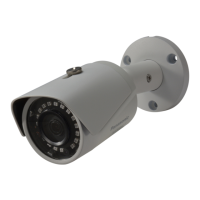
Attach the wall mount bracket to the wall that has the cable access hole and
caulk the bracket.
Pass the DC cable through the recessed area
of the water-resistant rubber and attach the
cable.
2-1 Open the cover. 2-2 Strip the DC cable.
2-3 Remove the water-resistant rubber (A) from the camera and attach it to the DC
cable.
2-4 Loosen the screws (
B) and push in the wires
of the DC cable to the terminal connectors
(non-polar), then tighten the screws.
● Recommended torque:
0.8 N·m {8.2 k
g
f·cm}
● Secure the water-resistant rubber attached to
the cable to its original position.
1-1 Secure the wall mount bracket.
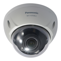
Install the camera
1
1-2 Use a water-resistant seal-
ant to caulk around the
bracket, except for the bot-
tom part.
● Mount the wall mount bracket so that the "
UP" mark faces up, and caulk as shown
here, making sure to ll in any gaps.
(If the bracket is not properly waterproofed, water may enter, which may result in fire
or electric shock.)
1-62, 4-chome, Minoshima, Hakata-ku, Fukuoka 812-8531, Japan
http://www.panasonic.net/
© Panasonic System Networks Co., Ltd. 2013
PNQW3991ZA PC1113MT1113
2
3
12 mm
32 mm
● Insert the wires while pressing the terminal buttons with the tip of a screwdriver.
Connect wires to the external input terminal.
● Refer to "About the external input terminal" on the reverse side and connect the wires
properly.
3-1 Strip the wires.
● Refer to 2-2 of step 2 for stripping wires.
3-2 Remove the water-resistant rubber (
C)
from the camera and attach it to the
wires.
● Refer to the drawing in 2-3 of step 2.
3-3 Connect the wires to the terminals (
D) and reattach
the water-resistant rubber and secure it in its original
position.
4
Close the cover (push closed until it clicks).
5
● After attaching the 4 screws
(accessory), attach the screw covers.
● Recommended torque:
1.2 N·m {12.2 k
g
f·cm}
Screws
(accessory)
Washer (accessory)
Safety
wire
Screw covers
(accessory)
Mounting screw
(locally procured)
Attach the camera to the wall mount bracket and secure it.
Adjusting the camera angle.
6
View when looking from below
● Recommended torque for screw
A
,
B
: 0.7 N·m {7.1 k
g
f·cm}
Adjusting angle left and right:
1. Loosen screw A and adjust the
angle left or right.
2. Tighten screw
A.
1. Hold the camera in one hand and
loosen screw
B to adjust the angle up
or down.
2. Tighten screw
B.
Adjusting angle up and down:
Turn on the camera, monitor the camera image, conrm the viewable area and the
camera audio. (
Operating Instructions of the Video Intercom System)
● If you’re not satised with the viewable area, adjust the camera angle and conrm the
results.
● If the Video Intercom System includes a sub monitor, take it to the camera installation
location and conrm the image displayed on the sub monitor while adjusting the camera
angle as necessary.
7
● Attach the safety wire high on the wall so
that the camera does not strike anyone in
the event the camera becomes detached
from the wall.
● Do not hang from the camera.
After you have adjusted the angle,
attach the safety wire to the wall.
8
9
Test the sensor detection and image recording. ( at right)
Lift the tab
to open the
cover
Water-resistant rubber
Cover
It is difficult to tighten the screw when the
camera is facing forward. Using the meth-
od shown to the right, tighten the screw
after rotating the camera body to the left or
right.
When tightening screws
View when looking
from below
Loosen this screw
and move the camera
left or right
Screw A
Screw B
When using the heat sensor
Using the sensor range caps Changing the angle of the heat sensor
If there are objects that you do not want the heat sensor to detect, you can limit the detectable
area by attaching the sensor range caps.
You can use the heat sensor adjustment lever on the camera to set the heat sensor to one
of two positions.
■ Sensor range cap types and detection range
In addition to the standard cap (already attached to the camera), there are four cap types
(caps 1-4). Each cap prevents a different area from being detected and can be attached
at 45-degree increments. Refer to the following and attach the proper cap at the proper
angle.
● The detection area is an approximation for when the [Heat sensor sensitivity] setting
(
"Changing the sensitivity of the heat sensor", below right) is set to [Normal].
(Varies by ambient temperature at camera installation location)
(Example 1)
When there is an object on the right side of
the viewable area that you do not want to
be detected (house next door, street, etc.).
Attach one of caps 1-3 as shown on the right
according to the area you do not want to be
detected.
(Example 2)
When there is an object in the top left of
the viewable area that you do not want
to be detected (cars in a street, etc.).
■ Removing and attaching sensor range caps
When removing:
Use the thick end of the cap removement tool (accessory) to remove.
When attaching:
Rotate the tab on the cap toward the
top or at a 45-degree angle according to
the type of cap or direction, and attach
the cap on the camera as shown on the
right.
Attach one of caps 1-3 as shown
above according to the area you
do not want to be detected
① ② ③
When using motion detection
Changing the detection range of the motion detection sensor
Changing the sensitivity of the motion detection sensor
Use the main monitor to change the camera’s [Motion detection range] setting.
● By setting the areas that you do not want motion to be detected from the 12 blocks shown in
the screen below, you can narrow down the areas that motion can be detected in.
Use the main monitor to change the camera’s [Motion detection sensitivity] setting. (You can
adjust the amount of motion that will be detected by setting the sensitivity setting.)
■ Motion detection sensitivity setting (4 levels)
● High sensitivity
● Normal (default setting)
● Low sensitivity
● Very low sensitivity
Changing the setting (Example: Video Intercom System VL-SWD501EX series)
Use the main monitor settings, select [Connected devices] → [Camera] → camera number
→ [Sensor settings] → [Motion detection range] → the areas not subject to detection from
the 12 blocks, and then touch [Configure].
(Example) When checking motion detection performance, a car in the street that
you do not want to be detected is displayed in the top of the screen
In the motion detection range screen, select the area containing the street that you do not
want to be detected.
Adjusting sensor sensitivity and detection range
Note:
● When [High sensitivity] is selected, it is more likely that wind or objects outside the
viewable area will cause detections. (Use this setting only when the installation
environment absolutely requires it)
Use the main monitor to change the camera’s [Heat sensor sensitivity] setting.
(
The heat sensor’s range of detection varies by the selected sensitivity.
)
■ Heat sensor sensitivity and detection range
The detection range shown below is an approximation. (Varies by ambient temperature
and environment of installation location)
High sensitivity:
Low sensitivity:
Normal (default setting):
■ Lever position and sensor detection range
The detection range shown below is an approximation. (Varies by ambient temperature
and environment of installation location)
At time of purchase:
When lever is raised:
Changing the sensitivity of the heat sensor
Use the main monitor settings, select [Connected devices] → [Camera] → camera
number → [Sensor settings] → [Heat sensor sensitivity] → the sensitivity from the 4 lev-
els.
Changing the setting (Example: Video Intercom System VL-SWD501EX series)
Very low sensitivity:
Ambient temperature: 20 °C
Use the main monitor settings, select [Connected devices] → [Camera] → camera
number → [Sensor settings] → [Motion detection sensitivity] → the sensitivity from the 4
levels.
Changing the setting (Example: Video Intercom System VL-SWD501EX series)
Cap type
Approximate detection range (view when looking from above)
20 ºC 0 ºC 30 ºC
Standard (attached
to camera)
Cap 1
(Example) Cap 1 (Example) Cap 1 (Example) Cap 1
Cap 2
(Example) Cap 3 (Example) Cap 3 (Example) Cap 3
Cap 3
When you want
to make one side
not detectable
Cap 4
When you want to
make both sides
not detectable
● The detection range rotates according to the sensor range cap angle.
Motion will not be detected in areas
with an "X".
Configure
>>>>>>Motion detection range
Touch the areas that you do not
want to detect motion for.
If you want to detect small changes in
motion, select [High sensitivity], and select
[Low sensitivity] or [Very low sensitivity] if you
want to detect only drastic changes in motion.
Detection
range
About 5 m
About 5 m
About 5 m
About 5 m
About 6 m
About 6 m
About 6 m
About 6 m
About 4 m
About 4 m
About 4 m
About 4 m
Detection
range
Example 1
Example 2
Detection
range
Tab
About 6 m
About 5 m
About 4 m
About 3 m
Detection
range
Detection
range
Detection
range
Detection
range
View from above
View from above
View from above
View from above
Lever
At time of purchase:
When the lever is raised:
Viewable area
Detection range
Viewable area
Detection range
Confirming sensor detections
From the top menu of the main monitor, touch → →
[Connected devices] → [Camera] → camera number → [Sensor settings] →
[Check sensors] → tap each type of sensor to confirm.
You must trigger the
sensor at the camera
within about 20 minutes.
To end the operation, press
.
1
2
3
Use the main monitor to confirm the detections made by the heat sensor or motion detection.
● The operations described here are based on the VL-SWD501EX series main monitor. See the
Operating Instructions of the Video Intercom System for more information.
● When sensors make a detection
–
The camera’s LED lights and indicator lamp
ash.
–
The display on the main monitor changes as
shown to the right according to the sensor type
selected in step 1.
Note:
● The camera image turns off automatically after about 20 minutes when conrming the sensor. If
20 minutes pass while conrming, start over from the beginning.
● You can also use the above procedure to conrm a commercially available external sensor, if
connected.
When detections are not made correctly or when incorrect detections are made
■ When detections are not made prop-
erly
Refer to "Adjusting sensor sensitivity and
detection range" (
at right) and make
adjustments as explained below.
Heat sensor:
● Change the [Heat sensor sensitivity]
setting (increase sensitivity)
Motion detection:
● Change the [Motion detection sensitivity]
setting (increase sensitivity)
■ When incorrect detections are made
Refer to "Adjusting sensor sensitivity and
detection range" (
at right) and make
adjustments as explained below.
Heat sensor:
● Use the sensor range caps
● Change the angle of the heat sensor
● Change the [Heat sensor sensitivity]
setting (decrease sensitivity)
Motion detection:
● Change the [Motion detection sensitivity]
setting (decrease sensitivity)
● Change the [Motion detection range]
setting (change the range)
Testing the sensor detection images
Confirm if images are correctly recorded before and after images are recorded for sensor detections.
● The operations described here are based on the VL-SWD501EX series main monitor. See the
Operating Instructions of the Video Intercom System for more information.
From the top menu of the main monitor, touch → →
[Connected devices] → [Camera]→ camera number → [Sensor settings] →
[Recording test].
You must trigger the
sensor at the camera
within about 20 minutes.
When recording ends, touch [Result] and
confirm the recorded images (A-D).
To end the operation, press
.
● A screen such as the one shown on
the right is displayed on the main
monitor, and images from when the
detection occurred are retained (up
to 4 still images).
● Touch an image (
A
-
D
) to display it full-
screen.
● To perform a recording test again, touch
in the screen shown to the right,
and touch [Test again] when the screen
in step 3 is displayed.
When using default setting:
A:
Image from 1 second before detection
B to D: Images from time of detection
until about 2 seconds after detection
You can use the
[Recording before detection] setting to
retain images from up to 2 seconds before
the detection. (
Operating Instructions
of the Video Intercom System)
The sensor name is displayed for
about 1 second. When the sen-
sor is triggered again, the name is
displayed.
■ Confirm with a subject that you want
to detect
Check whether the sensor is triggered at the
location where you want to detect movement,
with people moving in the direction you want
to detect.
■ Confirm with a subject that you do not
want to detect
Check whether the sensor is not triggered by
subjects that you do not want to detect, such
as people or cars moving on a street.
● The camera waits for the sensors to be triggered and live images from the camera are
displayed.
Motion detection:
Heat sensor:
Heat sensor
1
1
Motion detection
Area that motion was detected in (shown in yellow)
Displayed when recording is complete
Live image
(Example) When the heat sensor
makes a detection
ヒ
ヵㄆㄔㄕチㄈㄊㄏ
ンㄆㄔㄖㄍㄕ
ラㄆㄕチㄔㄆㄏㄔㄐㄓ
1
Result
①
②
③
④
1
4
3
1
5
Name of sensor which made the detection
Confirm the displayed message and then touch [Next].
● The camera waits for the sensors to be triggered.
2
■ About the installation location
● The device must be installed inside an electrical panel or cabinet.
● A readily accessible disconnect device shall be incorporated external to the equipment.
- External disconnect device must be certied and have a creepage and clearance
distance of 3 mm or more.
■ Precautions for wiring
● Make sure you turn off the power at the breaker before performing any wiring work.
● Always connect AC or DC cables to the appropriate connection terminals. Incorrectly
connecting the AC or DC cables may damage the power supply unit.
● To prevent the power cables from disconnecting and to prevent electric shock, secure the
power cables using the cable binders (accessory) and attach the cable covers.
B
A
D
C
CAUTION
Insert the cables firmly all the
way into the terminals.
If the cables are not inserted all
the way, heat may be generated.
*1 Make sure that there are no bare wires
exposed outside the product.
Connect the power supply unit (accessory) and AC/DC cables (locally procured).
1
Strip the AC/DC cables as follows:
7 mm
45 mm
<AC cable>
<DC cable>
25 mm
7 mm
2
Remove the screws (
B
) and then remove
the cable covers (
A
).
3
Connect the AC/DC cable to the AC IN
terminal/DC OUT terminal on the top and
bottom of the power supply unit, and then
secure the wires by tightening the screws.
● Recommended torque:
- AC terminal: 0.4 N·m {4.1 kgf·cm}
- DC terminal: 0.45 N·m {4.6 kgf·cm}
220-240 V AC
AC cable
*1
DC cable
24 V DC
Screws
*1
Cable binders (accessory)
4
Use the cable binders (accessory) to secure
the AC/DC cables (double-coated area) to
the power supply unit.
5
Make sure to replace the cable covers (
A
).
DC OUT terminal
AC cable
binder hole
AC IN terminal
<Top view>
<Bottom view>
DC cable
binder hole
Cable covers (
A
)
Screws (
B
)
Mounting screws
(locally procured) × 4
Vertical, flat wall
46 mm
83.5 mm
Cable access
hole
DC cable
Water-
resistant
sealant
Wall mount
bracket
Configure
>>>>>>Motion detection range
Touch the areas that you do not
want to detect motion for.
The bottom part of the bracket
has a water drain hole on it; do
not caulk it
Power supply unit (with cable covers
removed)
<Front view>
 Loading...