EasyManua.ls Logo

Panasonic WH-UD30BE5-1 User Manual

Panasonic WH-UD30BE5-1
85 pages
To Next Page IconTo Next Page
Page #1 background imageLoading...
Page #1 background image
© Panasonic HA Air-Conditioning (M) Sdn. Bhd. 2010.
Unauthorized copying and distribution is a violation of law.
Order No. PHAAM1002132C2
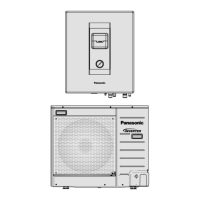
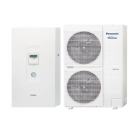
Air-to-Water Heatpump
Indoor Unit Outdoor Unit
WH-SD24BE5-1 WH-UD24BE5-1
WH-SD30BE5-1 WH-UD30BE5-1
TABLE OF CONTENTS
PAGE PAGE
1 Safety Precautions----------------------------------------------- 3
2 Specifications ----------------------------------------------------- 5
2.1. WH-SD24BE5-1 WH-UD24BE5-1-------------------- 5
2.2. WH-SD30BE5-1 WH-UD30BE5-1-------------------- 7
3Features------------------------------------------------------------- 9
4 Location of Controls and Components ------------------10
4.1. Indoor Unit--------------------------------------------------10
4.2. Outdoor Unit -----------------------------------------------12
5Dimensions--------------------------------------------------------13
5.1. Indoor Unit--------------------------------------------------13
5.2. Outdoor Unit -----------------------------------------------14
6 Refrigeration And Water Cycle Diagram-----------------15
7 Block Diagram --------------------------------------------------- 16
8 Wiring Connection Diagram--------------------------------- 17
8.1. Indoor Unit ------------------------------------------------- 17
8.2. Outdoor Unit----------------------------------------------- 18
9 Electronic Circuit Diagram----------------------------------- 19
9.1. Indoor Unit ------------------------------------------------- 19
9.2. Outdoor Unit----------------------------------------------- 20
10 Printed Circuit Board ------------------------------------------ 21
10.1. Indoor Unit ------------------------------------------------- 21
10.2. Outdoor Unit----------------------------------------------- 22
11 Installation Instruction ---------------------------------------- 24
11.1. Select The Best Location ------------------------------ 24

Table of Contents

Questions and Answers:

Panasonic WH-UD30BE5-1 Specifications

General IconGeneral
BrandPanasonic
ModelWH-UD30BE5-1
CategoryHeat Pump
LanguageEnglish

Summary

Safety Precautions

General Safety Guidelines

Covers warnings, cautions, and prohibited actions for unit servicing and operation.

Specific Safety Instructions

Detailed numbered safety requirements for installation, servicing, and handling refrigerant.

Specifications

WH-SD24BE5-1 / WH-UD24BE5-1 Specifications

Technical data for the outdoor unit model WH-SD24BE5-1 and WH-UD24BE5-1.

Indoor Unit Specifications

Technical data pertaining to the indoor unit of the heatpump system.

WH-SD30BE5-1 / WH-UD30BE5-1 Specifications

Technical data for the outdoor unit model WH-SD30BE5-1 and WH-UD30BE5-1.

Features

Product Features and Operation Details

Details key features like Inverter Technology, efficiency, design, environment, piping, control, quality, serviceability, and operation conditions.

Location of Controls and Components

4.1. Indoor Unit Controls and Displays

Details the indoor unit's control panel, buttons, indicators, and displays.

4.2. Outdoor Unit Components

Identifies and describes the main components of the outdoor unit.

Dimensions

Unit Dimensions

Provides overall dimensions for both indoor and outdoor units.

Refrigeration And Water Cycle Diagram

System Cycle Diagrams

Illustrates the refrigerant and water flow within the system.

Block Diagram

System Block Diagram

Shows the overall system connectivity and major functional blocks.

Wiring Connection Diagram

Wiring Diagrams: Indoor and Outdoor Units

Provides detailed wiring schematics for both indoor and outdoor units.

Electronic Circuit Diagram

Circuit Diagrams: Indoor and Outdoor Units

Illustrates the electronic circuit layouts for system components.

Printed Circuit Board

PCB Layouts: Indoor Unit Main Board

Shows the layout and component placement of the indoor unit's main PCB.

PCB Layouts: Outdoor Unit Boards

Shows the layout of outdoor unit's main, capacitor, and noise filter PCBs.

Installation Instruction

11.1. Installation Site Selection

Guidelines for selecting the optimal installation location for indoor and outdoor units.

11.2. Installation Diagrams and Guidelines

Visual guides and procedures for installing indoor and outdoor units, including piping.

11.3. Indoor Unit Installation Procedures

Covers fixing the installation plate, drilling holes, refrigerant piping, and water connections.

11.4. Outdoor Unit Installation Procedures

Covers unit mounting, piping, evacuation, cable connection, and insulation.

Operation and Control

12.1. Basic Operation Functions and Modes

Explains basic operation, temperature settings, heating modes, and fan control.

12.2. Water Pump and Flow Control

Details the operation of the water pump and the function of the flow switch.

12.3. Pump Down and Safety Features

Covers pump down operation, indoor unit safety controls, auto restart, and indication panel functions.

Protection Control

13.1. General Operation Protection Mechanisms

Explains protections for all operations, including current, IPM, compressor, and frequency limits.

13.2. Heating Operation Protection Mechanisms

Details protections specific to heating operation, such as air temperature and deice controls.

Servicing Mode

Servicing Procedures and Adjustments

Covers test run procedures, proper pump down, and water flow rate adjustments.

Maintenance Guide

Water Pressure, Filter, and Valve Maintenance

Covers checks on water pressure, water filter cleaning, and pressure relief valve operation.

Electrical Checks and Air Release

Covers control board inspection, RCCB testing, and releasing trapped air from the water circuit.

Troubleshooting Guide

16.1. System Analysis and Error Codes

Covers refrigeration cycle issues, unit condition analysis, self-diagnosis function, and error code table.

16.5. Common Malfunction Troubleshooting

Details troubleshooting steps for various sensor, communication, component, and system faults.

Disassembly and Assembly Instructions

17.1. Removing Front Plate and Cabinet

Step-by-step instructions for removing the front plate and cabinet covers.

17.3. Component Removal Procedures

Covers removal of pressure gauge, control panel, controller board, transformer, and RCCB.

17.7. Removing Water Circuit Components

Instructions for removing the pressure relief valve, flow switch, and water pump.

Technical Data

18.1. Operation Characteristics (Model 1)

Performance data for WH-SD24BE5-1 / WH-UD24BE5-1 at various conditions.

18.1. Operation Characteristics (Model 2)

Performance data for WH-SD30BE5-1 / WH-UD30BE5-1 at various conditions.

18.2. Heating Capacity Table

Table detailing heating capacity at different ambient and water temperatures.

18.3. Hydraulic Pump Performance Curve

Graph showing the relationship between water flow rate and external static pressure.

Exploded View and Replacement Parts List

19.1. WH-SD24BE5-1 / WH-SD30BE5-1 Parts List

Exploded view and replacement parts list for the indoor unit models.

19.2. WH-UD24BE5-1 / WH-UD30BE5-1 Parts List

Exploded view and replacement parts list for the outdoor unit models.

Related product manuals