EasyManua.ls Logo

Panasonic YA-1WAR61U Series - User Manual

Panasonic YA-1WAR61U Series
72 pages
Print Icon
To Next Page IconTo Next Page
Loading...
Before operating this product, please read the instructions carefully and save this manual for future use.
Please read the operating instructions of peripheral equipment together with it.
First of all, please read “Safety precautions”.
English version is the original instructions.
2010
Operating Instructions
Model No. YA-1W/YA-1Z/YA-2E/YA-2G Series
TAWERS WGH 450 A Type
- The Arc Welding Robotic System -
Model No.
YA-1WAR61T**
YA-1WAR61Y**
YA-1WAR61E**
YA-1WAR61U**
(TM-1400/TM-1100/TM-1600)
YA-1WAR81T**
YA-1WAR81Y**
YA-1WAR81E**
YA-1WAR81U**
(TM-1800/TM-2000)
YA-1ZAR81T**
YA-1ZAR81Y**
YA-1ZAR81E**
YA-1ZAR81U**
(TL-1800/TL-2000)
YA-2EAR81T**
YA-2EAR81Y**
YA-2EAR81E**
YA-2EAR81U**
(TS-800/TS-950)
YA-2GA261T**
YA-2GA261Y**
YA-2GA261E**
YA-2GA261U**
(LA-1800)
OM1305066E26
Arc Welding Robot Controllers

Table of Contents

Question and Answer IconNeed help?

Do you have a question about the Panasonic YA-1WAR61U Series and is the answer not in the manual?

Summary

Operating Instructions

Introduction and Safety

Safety Precautions

Provides essential safety information and precautions for operating the robot system.

Safety Precautions

Safe Welding Operation Guidelines

Details crucial safety guidelines for welding operations, covering power units and electric shock hazards.

Safety Precautions

Hazard Prevention: Fire, Explosion, Ventilation

Covers prevention of fire, explosion, ventilation needs, and handling of gas cylinders.

Specifications Overview

Technical Specifications

Controller Inputs, Outputs, and Communication

I;O, Safety Circuit, and Interface Details

Details the status I/O, common I/O, safety circuit, and communication interfaces.

Welding Power Source Specifications

Digital Welding and Static Characteristics

Lists specifications for the built-in digital welding power source and its static characteristics.

Teach Pendant Specifications

Teach Pendant Features and Connectivity

Details the specifications of the Teach Pendant, including display, memory, and ports.

Operation Box Specifications

Operation Box Features and Functionality

Describes the specifications and functionality of the operation box.

Controller Accessories

Installation Procedures

Installation Details

Connection Procedures

Controller to Manipulator Connection

Guides on connecting the motor and RE cables between the controller and manipulator.

Connection Details

Power Source and Multi-Robot Connections

Details connecting power source cables and notes for using multiple robots.

Teach Pendant Connection

Teach Pendant Cable Connection

Guides on connecting the teach pendant cable, emphasizing careful handling and proper alignment.

Grounding Connections

Protective Earth Grounding Requirements

Instructs on providing exclusive protective earth (PE) grounding for the controller and its specifications.

Power Source Connection

Primary Power Wiring and Noise Prevention

Explains connecting the primary power source, including breaker and filter requirements.

Primary Power Wiring (T*;Y* Spec.)

Primary Power Wiring (E*;U* Spec.)

Lock Switch Procedures

External Device Connection

Connecting External Devices and Noise Control

Advises on connecting external devices, protecting against noise, and using shield wires.

Noise Filter Unit Usage

Safety I;O Specifications

Safety Circuit I;O Details

Explains the dual circuit application for safety and the use of safety I/O card components.

Spare Emergency Stop Input

Describes the spare emergency stop input terminal as the highest safety level for external devices.

Safety I;O Input Functions

External Emergency Stop and Door Stop Inputs

Details external emergency stop and door stop inputs for safety fence interlocks.

Safety I;O Protective Stop and Enabling

Safety Circuit Input Overview

Schematic of Safety Circuit Inputs

Illustrates the safety circuit inputs, including emergency stops, enabling switches, and door stops.

Safety I;O Output Specifications

Emergency Stop Output Signals

Describes the output terminals that signal the emergency stop state, including reserved outputs.

Other Safety I;O Functions

External Control Signals

I;O Terminal Equivalent Circuits

Input and Output Circuit Diagrams

Illustrates equivalent input and output circuits for T/Y/U and E specifications.

Status Inputs and Outputs

Status Output Signals

External Interfaces

Welding Monitoring

Maintenance and Inspection

Inspection Schedule and Procedures

Outlines the inspection schedule for ensuring full functions, performance, and safety of the robot.

Daily Maintenance Checks

Pre-Power On Checks

Lists inspections to be performed before turning on the power, including checking cables, manipulator, and filters.

Post-Power On and Periodical Checks

Checks After Power On and Periodical Inspections

Details checks after turning on power and periodical inspections for components.

Repair Parts Identification

Controller Component Locations

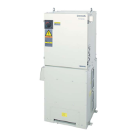
Provides a diagram showing the locations of various controller parts for repair.

Controller Component Part Numbers

Teach Pendant Repair Parts

Operation Box Repair Parts

Circuit Diagrams

Circuit Diagrams

Label Details and Warnings

Panasonic YA-1WAR61U Series Specifications

General IconGeneral
BrandPanasonic
ModelYA-1WAR61U Series
CategoryIndustrial Equipment
LanguageEnglish

Related product manuals