EasyManua.ls Logo

Pandora Smart Moto User Manual

Pandora Smart Moto
56 pages
To Next Page IconTo Next Page
Page #1 background imageLoading...
Page #1 background image
Pandora would like to thank you
for choosing our service-security system
for motorcycles Pandora Smart Moto/Smart Moto Plus
Pandora Smart Moto / Smart Moto Plus is a service-security system built for motorcycles and
quads with on-board voltage of 12V.
It is a complex engineering device, which includes unique and modern technological software and
hardware solutions. While developing we were using the most up-to-date electronics from world’s
best manufacturers. The device is built using high-precision mounting and control machinery; thus,
we guarantee highest possible quality, reliability and stable technical characteristics for the whole
operation period.
The system is built for your convenience: it’s ergonomic, reliable, has the highest security and service
characteristic
s, 3 years unconditional warranty and free service and support. We are happy to provide
any support we can – feel free to use our online support.
! WARNING! I T IS STRONG LY RECOMME NDED TO HAVE A PROFESS IONAL CAR MECH ANI C TO INSTALL THE SYSTEM . A NY
CAR ELECT RONICS INSTALLE R SHOULD BE ABLE TO INSTALL THE SYSTEM USING INSTALL ATION SCHEME IN THIS MAN UAL
AND THE ALAR M STUD IO OR PANDORA SPEC IA LIST SOFT WAR E. MOST FE ATURES AR E HIGHLY DEPE NDENT ON COMPETE NT
INSTALL ATION. OUR SYSTEMS ARE THO ROUGHLY TESTED FOR QUALITY , SO IF A FE ATURE FAILS TO PRODUCE EXPECTED RESULT ,
MOST LIKELY THE PROBLEM IS IN IMP ROPE R INSTALLATION.
This device has limited external factors resistance. It should not be subjected to water beyond occasional splatter.
The base unit is designed to operate at temperatures from -40°C to +85°, the degree of protection is IP54.
The control units (remotes, tags, etc.) are designed to operate at temperatures from -10°C to +40°C, the degree of protection is IP40.
See wiring diagram to nd information about additional devices and options.
Our web-site: pandorainfo.com
Customer support: support@pandorainfo.com
Product is in conformity with Electromagnetic Compatibility
Directive EMC 2004/108/EC and R&TTE Directive 1999/5/EC
Question and Answer IconNeed help?

Do you have a question about the Pandora Smart Moto and is the answer not in the manual?

Pandora Smart Moto Specifications

General IconGeneral
GPS/GLONASSYes
ImmobilizerYes
Anti-hijackYes
Alarm SystemYes
GPS TrackingYes
Smartphone ControlYes
Battery BackupYes
Two-Way CommunicationYes
Shock SensorYes
Tilt SensorYes
MicrophoneYes
SirenYes
Operating Temperature-40°C to +85°C
BluetoothYes
GSMYes
Mobile applicationYes (iOS and Android)
Operating Voltage12V DC

Summary

System installation

General installation requirements

Instructions for installing the system correctly and safely.

Base unit connectors description

Details on the connectors of the base unit for system wiring.

Wiring diagram

Visual representation of system connections and component wiring.

Online service and mobile application

Registration

Steps to create an account for online and mobile services.

Login

How to access the online service and mobile application.

Adding a system to your account

Process of linking the security system to a user account.

Writing a mobile device to the system memory

Pairing a mobile phone for control or as an authorization device.

Control the system

Arming

Methods to arm the security system.

Disarming

Methods to disarm the security system.

PANIC mode

How to activate the panic function for attention.

Vehicle search function

Feature to locate the vehicle in a parking area.

Season storage mode

Mode for long-term parking to reduce power consumption.

Service mode

Mode for maintenance without system interference.

Control over the system in case of emergency

Emergency disarming

Procedures for disarming in emergency situations.

Emergency control of the anti-theft functions

Managing anti-theft features during emergencies.

Programming the system

Pandora Specialist Application

Using the mobile app for system configuration.

Pandora Alarm Studio

Using PC software for system configuration and updates.

Updating firmware

Instructions for updating the system's software.

Programming table

Reference table for system programming commands.

Additional devices

Information on compatible extra devices

Information on compatible extra devices.

Warranty obligations

Installation certificate

Document for installer to certify system installation.

Acceptance certificate

Certificate confirming system conformity and acceptance.

Warranty Card

Document detailing warranty terms and conditions.

GENERAL INFORMATION

System set Pandora Smart Moto and Pandora Smart Moto Plus

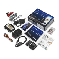
Lists all components included in the system package.

Read before using

Safety Precautions

Important warnings and advice before starting installation and use.

System Installation Guidelines

Recommendations for professional installation and checks.

Owner's Personal Card Handling

Instructions on how to handle and use the owner's personal card.

PIN-codes of the system

Secret PIN-code

Details of the secret PIN-code and its use.

Service PIN-code

Information on the service PIN-code and its default value.

Guest PIN-code

Details on the guest PIN-code and its default value.

Immobiliser PIN-code

Use of the immobiliser PIN-code for specific functions.

System modules layout

External VALET button

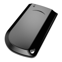
Description and illustration of the external VALET button.

Base unit

Description and illustration of the base unit.

Siren

Description and illustration of the siren.

Owner's personal card

Handling and Information

Instructions for careful handling and information contained on the card.

PIN, LOGIN, PASS, Phone Number Details

Explains the purpose of PIN, Login, Pass, and Phone number on the card.

External VALET button

Description and Functionality

Details on the external VALET button's features and usage.

Base unit

LTE, GPS, GLONASS Module

Functionality of the LTE, GPS, and GLONASS module.

Nano-SIM Port

Information about the nano-SIM port and its usage.

2.4GHz Radio Channel and Bluetooth 5.0

Details on Bluetooth connectivity and features.

3D Accelerometer

Functionality of the 3D accelerometer for shock/motion detection.

Temperature Sensors

How temperature sensors measure and report vehicle temperatures.

Built-in Battery

Function of the internal battery for power outages.

Micro-USB Port

Use of the micro-USB port for updates and configuration.

Information signals of the system

Sound and Light Signals

Table detailing system signals (sound/light) and their meanings.

EXTERNAL BUTTON LED INDICATOR SIGNALS

System Armed Status

LED signals indicating when the system is armed.

System Disarmed Status

LED signals indicating when the system is disarmed.

PIN Code Entry Signals

LED signals related to PIN code entry.

SYSTEM FUNCTIONS AND MODES

Security mode

Explanation of how the security mode operates and its signals.

Security zones

List of Monitored Zones

Details of various zones monitored by the system.

Owner authorization devices and functions

Authorization Devices Overview

Information on devices used for owner authorization.

Arming/Disarming by Clutch Lever

How to arm/disarm using the clutch lever.

Hands Free Arming/Disarming

Automatic arming/disarming via authorization device proximity.

Immobiliser mode

Functionality and Operation

How the immobiliser mode works with authorization devices.

Anti-Hi-Jack mode

Purpose and Operation

How the Anti-Hi-Jack mode prevents vehicle seizure.

Code Immobiliser (pin-to-drive) function

How to Use the Function

Steps and examples for using the pin-to-drive immobiliser.

Checking the number of paired devices

LED Indicator Method

Using LED flashes to check paired devices.

Battery Terminal Method

Checking paired devices by manipulating the battery terminal.

IMMOBILISER RADIO TAG

Description and Components

Overview of the radio tag, its components, and features.

Button Functions and Actions

Detailed mapping of button presses to system functions.

Indication of the SEND LED

LED Signal Meanings

Interpretation of different SEND LED indications.

Installation/replacing a battery of the tag CR2032

Battery Replacement Procedure

Step-by-step guide for changing the tag's battery.

Prompt entry/change of the main owner phone number

Procedure for Phone Number Update

Steps to change the main owner's phone number.

Updating firmware of the tag

Firmware Update Process

Instructions for updating the radio tag's firmware via mobile app.

PANDORA BAND

Wristband Description and Features

Overview of the Pandora Band, its specifications and capabilities.

Switching the Band On/Off

How to power the Pandora Band on and off.

Charging the Band

Instructions for charging the Pandora Band's battery.

Button's functions

Band Button Operations

Mapping of button presses on the Pandora Band to functions.

Firmware update

Band Firmware Update Process

Steps for updating the Pandora Band's firmware.

Information icons

Icons for System Status and Sensors

Explanations of various icons displayed by the system.

CONTROL THE SYSTEM BY A PHONE

Command Codes List

Table of command codes for controlling the system via phone.

Voice Help Commands

Instructions for using voice commands to control the system.

Changing settings via a phone

Phone Number Settings

Adjusting phone number settings for notifications and control.

Additional Settings

Configuration of guest PIN and text message thresholds.

Voice call settings

Configuring voice call notifications for different events.

Sensor sensitivity settings

Adjusting sensitivity levels for various sensors.

Saving mode settings

Settings related to GSM connection saving modes.

Current time and date settings

Adjusting the system's time and date.

Micro-USB connector

Purpose and Connection

Use of the micro-USB connector for configuration and updates.

Main cable

Wire Descriptions and Functions

Detailed explanation of each wire in the main cable harness.

BASE UNIT

Base Unit Placement Guidelines

Recommendations for installing the base unit in the vehicle.

Antenna and Component Details

Information on antennas, micro-USB, battery, and SIM card.

Wiring Diagram Overview

Visual overview of the base unit's wiring connections.

WIRING DIAGRAM

System Installation Warnings

Critical warnings regarding system installation and voltage.

Component Connections

Detailed diagram showing connections for power, sensors, and outputs.

ONLINE SERVICE AND MOBILE APPLICATIONS

Telemetric Control Options

Using online service and mobile app for vehicle control.

Account Creation and System Linking

Process for registering and adding the system to your account.

Registration

Account Registration Procedure

Steps to create a new user account for the service.

Login

Accessing Online Services

How to log in to the online service or mobile app.

Adding a system to your account

Linking System to User Account

Guide to add the security system to an existing user account.

Writing a mobile device to the system memory

Bluetooth Pairing Procedure

Steps to pair a mobile phone with the system via Bluetooth.

VEHICLE/SYSTEM ZONES

Controlled and Security Zones

Overview of system zones and their control status.

Notification Options by Zone

Types of notifications (voice, SMS, push) for each zone.

CONTROL THE SYSTEM

Arming the System

Various methods to arm the system when the ignition is off.

Disarming

Disarming the System

Different methods to disarm the security system.

HandsFree Mode Operation

How HandsFree mode functions for arming/disarming.

VALET Button Disarming

Using the VALET button for system disarming.

PANIC mode

Activating PANIC Mode

How to activate PANIC mode using various methods.

Vehicle search function

Using Vehicle Search

How to use the vehicle search function to locate the bike.

Season storage mode

Activating Season Storage

Procedures and conditions for activating season storage mode.

Service mode

Entering Service Mode

How to put the system into service mode for maintenance.

CONTROL OVER THE SYSTEM IN CASE OF EMERGENCY

Emergency System Control via Phone

Using phone commands for emergency control and disarming.

Emergency Deactivation Methods

Using VALET button and PIN-code for emergency deactivation.

Owner's personal card

PIN-code Entry Procedure

Detailed steps for entering the PIN-code using the VALET button.

External VALET button

PIN-code Entry via VALET Button

Specific instructions for PIN entry using the VALET button.

Emergency disarming

Procedure for Correct PIN Input

Steps to correctly input the PIN for emergency disarming.

Emergency control of the Code Immobiliser

Option 1: Temporary Deactivation

Temporarily deactivating Code Immobiliser using Secret PIN.

Option 2: Permanent Deactivation

Permanently deactivating Code Immobiliser via programming.

PROGRAMMING THE SYSTEM

Entering and Exiting Programming Mode

Steps to enter and exit the system's programming mode.

Pandora Specialist application

Configuration via Bluetooth

Using the app via Bluetooth for system configuration.

Configuration via USB-OTG

Using the app via USB-OTG for system configuration.

Pandora Alarm Studio

System Configuration and Updates

Using PC software for system settings and firmware updates.

Updating firmware

Pandora Specialist App Firmware Update

Updating firmware using the Pandora Specialist mobile app.

Pandora Alarm Studio Firmware Update

Updating firmware using the Pandora Alarm Studio PC software.

Programming table

VALET Button Programming Commands

Table detailing VALET button sequences for programming functions.

Level №0 – Entering a level

Navigating Programming Levels

How to enter and navigate through programming levels.

Level №2 – Changing the Service PIN-code

Service PIN-code Update Procedure

Step-by-step process to change the Service PIN-code.

Level №4 – Reset to the factory settings

Factory Reset Procedure

How to reset the system to its original factory settings.

Level №10 – Manage Bluetooth devices / Firmware Update

Pairing Additional Devices

Procedure for pairing various additional devices.

Level №10 – Manage Bluetooth devices / Firmware Update

Pairing Radio Tags

Steps to pair Pandora radio tags.

Pairing Pandora Band

Steps to pair the Pandora Band.

Pairing Door Sensor

Steps to pair Pandora door sensors.

Pairing Siren

Steps to pair Pandora sirens.

Updating Firmware of Additional Device

How to update firmware for additional devices.

Level №11 – Programming and configuring an «Immobiliser PIN-code»

Selecting Buttons for Immobiliser

Choosing buttons for Immobiliser function configuration.

Entering the Immobiliser PIN-code

Procedure for programming the Immobiliser PIN-code.

Level №13/№15 – Emergency deactivating/activating authorization devices and functions

Emergency Authorization Device Control

Emergency control for authorization devices and functions.

Level №50 – Pairing a mobile phone

Mobile Phone Pairing Procedure

Detailed steps for pairing a mobile phone.

Level №100 – Exit the programming menu

Exiting Programming Mode

Methods to exit the system programming mode.

ADDITIONAL DEVICES

Remote Control D-035

Information about the D-035 remote control and its features.

Radio tag BT-760 / BT-770 / BT-780

Details on the BT-760/770/780 radio tags.

Piezo siren PS-331 BT / PS-332 BT

Information on PS-331 BT and PS-332 BT piezo sirens.

WARRANTY OBLIGATIONS

Manufacturer's Warranty Terms

Conditions and terms of the manufacturer's warranty.

Loss of Warranty Rights

Situations where warranty rights may be lost.

Warranty Period and Limitations

Duration of warranty and exclusions like batteries.

Installation certificate

Installer's Certification Statement

Statement by the installer confirming correct installation.

Vehicle and System Specifications

Fields for car model, VIN, system serial number, etc.

Signatory and Acceptance Details

Signatures and acceptance confirmation for the installation.

Acceptance certificate

Product Conformity Statement

Statement confirming the product meets EMC and R&TTE directives.

Production and Packaging Details

Fields for serial number, date of production, and packager.

Warranty card

Purchase and Seller Information

Fields for serial number, date of purchase, and seller details.

Related product manuals