8
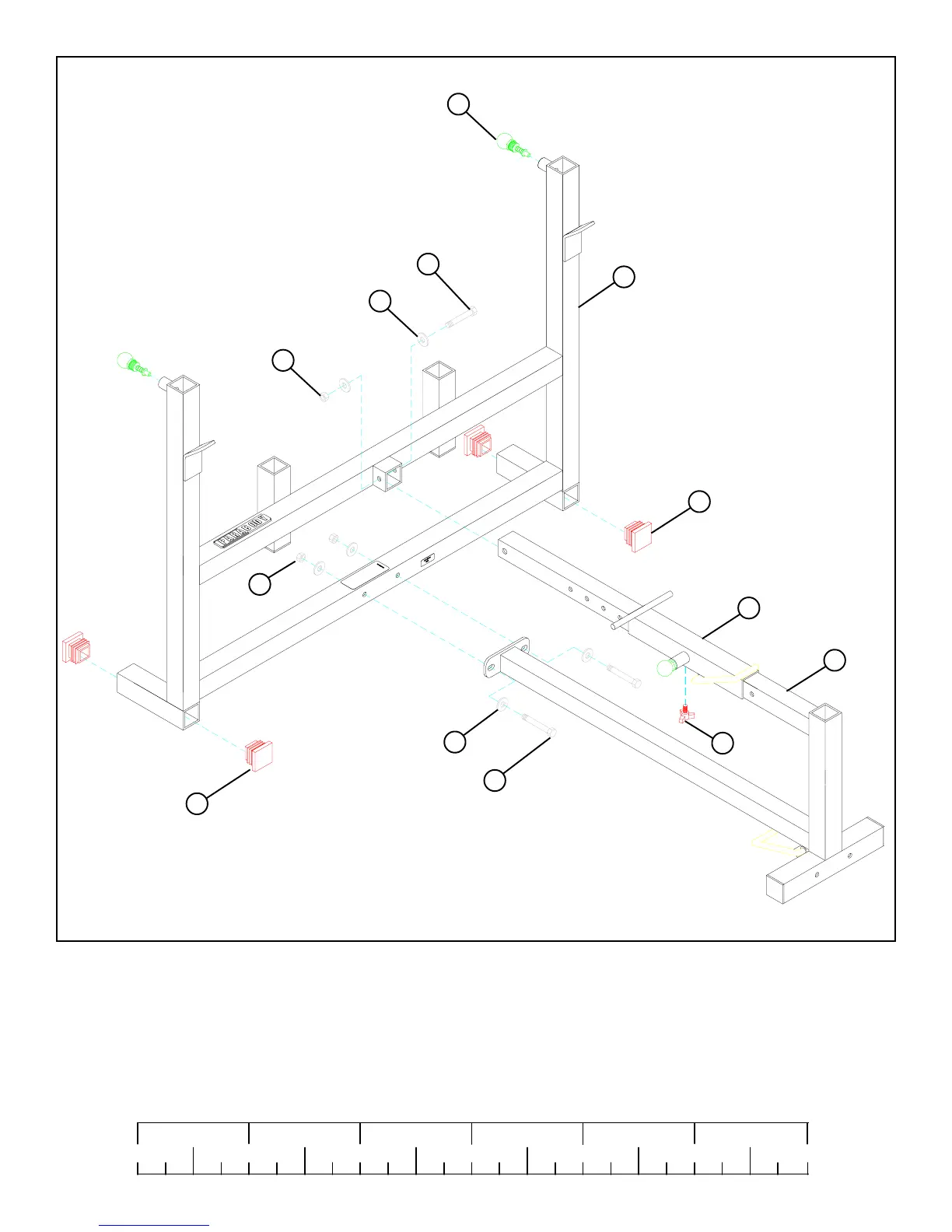
FIGURE 3
33
33
1
STEP 3:
• Secure the WOLFF SLEEVE (4) in place with one THUMBSCREW (29).
• Insert four 2” SQ. END CAPS (33) into the BASE TUBES of the UPRIGHT FRAME (1) as shown in FIGURE 3.
• SECURELY assemble the BENCH FRAME (2) to the UPRIGHT FRAME (1) using two 3/8 X 3” BOLTS (17), one 3/8 X 2-3/
4” BOLT (16), six 3/8” WASHERS (19), and three 3/8” LOCK NUTS (21) as shown in FIGURE 3.
4
2
21
19
3/8 X 3” 17
19
3/8 X 2-3/4” 16
21
0
1
2
345
6
1/2 1/2 1/2 1/2 1/2 1/2
29
25
• SECURELY assemble two 3/8” SPRING PIN ASSEMBLIES (25) to the SPRING PIN HOUSING on the UPRIGHT FRAME (1)
as shown in FIGURE 3. (NOTE: !!!IMPORTANT!!! Tighten the nut of the SPRING PIN ASSEMBLY SECURELY!)