7
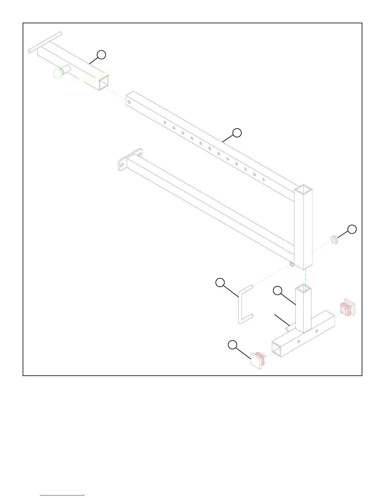
FIGURE 2
STEP 2:
4
10
5
2
• Pull back the SPRING PIN on the WOLFF SLEEVE (4) and slide it over the end of the BENCH FRAME (2) as shown in
FIGURE 2. Engage the SPRING PIN into one of the adjustment holes.
• Insert two 2” SQ. END CAPS (33) into both ends of the BASE LEG (5) as shown in FIGURE 2.
• Insert one U-PIN (10) through the BUSHING on the bottom of BENCH FRAME (2) and attach one PAL NUT (28) to the end of
the U-PIN (10) as shown in FIGURE 2.
• Insert the BASE LEG (5) into the front of the BENCH FRAME (2) as shown in FIGURE 2. (MAKE SURE THAT THE TAB
ON THE BASE LEG IS UNDER THE BENCH FRAME)
TAB
33
28