6
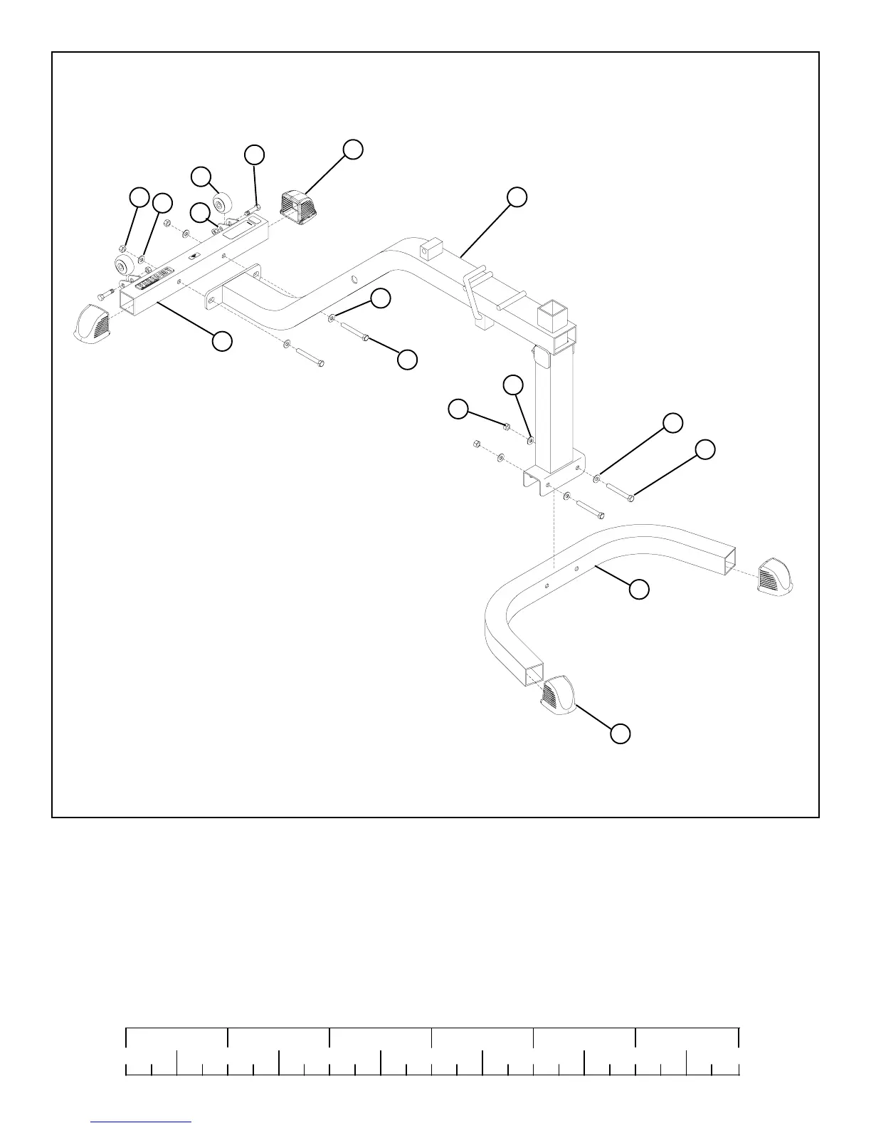
FIGURE 2
STEP 2:
0
1
2
345
6
1/2 1/2 1/2 1/2 1/2 1/2
• SECURELY assemble the FRONT BASE (6) to the BENCH FRAME (1) using two 3/8 X 3” BOLTS (18), four 3/8” WASHERS (19),
and two 3/8” LOCK NUTS (20). See FIGURE 2.
• Slide four 2” SQ. COVER CAPS (15) over the ends of the FRONT & REAR BASE (6 & 7) as shown in FIGURE 2.
1
6
20
19
19
15
7
19
20
15
19
18 3/8 X 3”
18 3/8 X 3”
• SECURELY assemble the REAR BASE (7) to the BENCH FRAME (1) using two 3/8 X 3” BOLTS (18), four 3/8” WASHERS (19), and
two 3/8” LOCK NUTS (20). See FIGURE 2.
• SECURELY assemble two WHEELS (30) to the REAR BASE (7) using two 3/8 X 1-3/4” BOLTS (31) and two 3/8” LOCK NUTS (20) as
shown in FIGURE 2.
31 3/8 X 1-3/4”
30
20