Do you have a question about the ParaBody GS6-LP5A-101 and is the answer not in the manual?
Key safety precautions and warnings for operating the equipment.
List of tools needed for the correct assembly of the product.
Illustration and explanation for measuring bolt lengths.
Attaching the connecting tube to the base using specified hardware.
Mounting the pulley housing to the base of the unit.
Instruction to remove and discard the existing lat cable.
Attaching pulleys and routing the lat cable through the top plate assembly.
Attaching the leg press cable to the floating pulley bracket and pulley housing.
Routing the leg press cable and securing pulleys to the bracket.
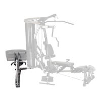
Securing the bracket from the leg press to the seat frame.
Attaching a pulley to the seat frame bracket with cable routing.
Securing a pulley to the seat frame with cable routing.
Attaching a pulley to the main arm with cable routing.
Connecting the leg press cable to the seat frame with specific tightening instructions.
Setting cable tension by pushing head plate and inserting weight pin.
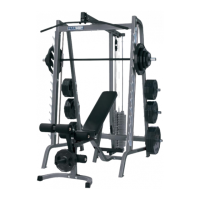
This document is a user's guide for the PARABODY LEG PRESS ADAPTER KIT FOR GS6 GYM SYSTEM, identified by Version: GS6-LP5A-101 and Revision: 11/01/02. The kit is designed to be an attachment for the PARABODY GS6 GYM SYSTEM, enhancing its functionality by adding a leg press station.
The PARABODY LEG PRESS ADAPTER KIT (LP5) converts a standard GS6 GYM SYSTEM into a comprehensive leg press station. This allows users to perform leg press exercises, targeting major muscle groups in the legs, including quadriceps, hamstrings, and glutes. The adapter kit integrates with the existing cable system of the GS6 GYM SYSTEM, utilizing its weight stack for resistance. The assembly process involves modifying the existing cable routing of the GS6 system, specifically by replacing the original LAT CABLE with a new one and rerouting it through a series of pulleys and brackets to power the leg press mechanism.
The manual provides a detailed parts list for the adapter kit, including various bolts, washers, nuts, pulleys, cables, and structural components. Key components include:
The manual emphasizes that bolt length is measured from the underside of the head of the bolt, providing a ruler graphic for accurate measurement.
The primary usage feature is the addition of a dedicated leg press station to the existing GS6 GYM SYSTEM. This allows for a compound exercise that targets multiple lower body muscles simultaneously. The design integrates the leg press mechanism with the gym's weight stack, providing adjustable resistance for users of varying strength levels.
The manual highlights several important safety and maintenance points that are crucial for the longevity and safe operation of the equipment:
The manual also stresses the importance of assembling the product on a flat, level surface and not securely tightening any frame connections until the entire frame has been assembled, unless otherwise stated. This ensures proper function and alignment of the components. Obtaining a medical exam before starting any exercise program is also recommended.
| Brand | ParaBody |
|---|---|
| Model | GS6-LP5A-101 |
| Category | Fitness Equipment |
| Language | English |