EasyManua.ls Logo

Paradox NV5 - User Manual

Paradox NV5
2 pages
Print Icon
To Next Page IconTo Next Page
Loading...
NV5 Installation Instructions
NV5-EI02 - 09/2019
Please read all installation instructions before installing the unit.
Figure 1: NV5 Back Plate
1. Select detector location using Figure 2 as a guide. The detector must be installed at
2.1m (7.0 ft) or higher.
Figure 2: Beam Pattern
2. Loosen the locking screw (9), located at the bottom of the unit.
3. Separate the front cover from the back plate.
4. Separate the PCB board from the back plate
5. On the back plate drill holes for the wire pass-thru (2) and appropriate knockou t hol es.
For wall mount drill holes (3), (10) and (15).
For corner mount drill holes (5), (7), (12) and (14).
For bracket mount drill hole (4).
6. Secure back plate to surface.
For wall mount, pass wires through hole (2) of the back plate and secure with screws at
(3), (10) and (15).
For a corner mount, pass wires through hole (2) of the back plate and secure with
screws at (5), (7), (12) and (14).
Figure 3: SB100 Bracket Assembly Installation
For bracketed ceiling mount (with SB100), insert ceiling accessory (21) and orient as
per (23). Insert the Bracket Retainer (25).Pass wire from ceiling through(25),through
(17) and through hole (2) of the back plate. Secure bracket to ceiling with screws at
(16). Secure back plate with a screw at (4) onto bracket at (18).
For bracketed wall mount (with SB100), insert wall accessory (22) and orient as per
(24). Pass wire from wall through (25), through (20) and through hole (2) of the back
plate. Secure bracket to wall with screws at (16) Secure back plate with a screw at (4)
onto bracket at (19).
7. Snap the PCB board onto the back plate.
8. Connect wires to terminal board (1) as per Figure 4.
Figure 4: Terminal Board Wiring
Callout Description
16 Bracket mounting holes
17 Wire pass-thru (ceiling)
18 Ceiling mount
19 Wall mount
20 Wire pass-thru (wall)
21 Ceiling Accessory
22 Wall Accessory
23
Ceiling Accessory
Orientation
24 Wall Accessory Orientation
25 Bracket Retainer
ALARM OUTPUT
N.C. COM BLK RED TAMPER
12 Vdc N.C.
Callout Description
1 Terminal board
2 Wire pass-through
3 Wall mount (knockout)
4 Bracket mount (knockout)
5 Corner mount (knockout)
6 Trimpot (sensitivity 1-5)
7 Corner mount (knockout)
8 Tamper switch
9 Locking screw
10 Wall mount (knockout)
11 Sensor
12 Corner mount (knockout)
13 Jumpers (profile/LED)
14 Corner mount (knockout)
15 Wall mount (knockout)
Question and Answer IconNeed help?

Do you have a question about the Paradox NV5 and is the answer not in the manual?

Summary

NV5 Installation Overview

Detector Location and Placement

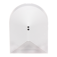
Select detector location based on beam pattern and install at 2.1m (7.0 ft) or higher.

Physical Installation Steps

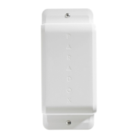
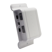
Instructions for loosening the unit, separating covers and PCB, preparing the back plate, and securing to surfaces.

Bracketed Mount Installation

Guidance for ceiling or wall mounting using the SB100 bracket assembly.

Terminal Board Wiring

Connect wires to the terminal board according to the provided diagram.

Configuration and Settings

Jumper Settings for Profiles and LED

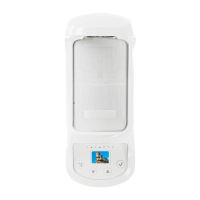
Adjust jumpers for 4 pre-programmed profile settings and LED ON/OFF.

Sensitivity Trimpot Adjustment

Configure sensitivity using the trimpot, adjusting from 1 to 5 for different detection ranges.

Installation Recommendations and Notes

Installation Recommendations

Avoid locations with temperature fluctuations, airflow changes, or dust accumulation.

Important Notes

Information on mirror options, SB100 bracket, and sensor maintenance.

Technical Specifications and Legal Information

Technical Specifications

Details on installation height, current consumption, power input, coverage, and operating conditions.

Legal and Warranty Information

Information on patents, trademarks, certification, and warranty statements.

Overview

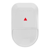
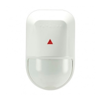
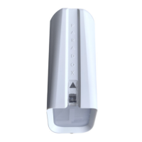
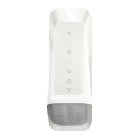
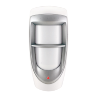
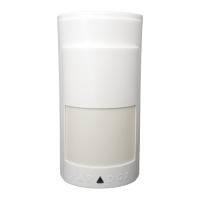
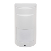
The NV5 is a motion detector designed for security applications, featuring advanced detection capabilities and flexible installation options. It is suitable for both residential and commercial environments, offering reliable intrusion detection with features to minimize false alarms.

Function Description:

The NV5 detector utilizes passive infrared (PIR) technology to sense motion within its coverage area. It is designed to detect the movement of people while offering pet immunity to prevent false alarms from small animals. The device can be configured with different profiles to adapt to various environmental conditions and security requirements, including settings for normal environments, moderate interference, pet-resistant applications, and harsh environments with high potential interference.

The detector processes signals based on either "single" or "dual" beam crossing, allowing for increased detection performance and false alarm rejection. The "single" processing type is suitable for partially crossing the beam, while "dual" requires full beam crossing for increased detection performance.

Important Technical Specifications:

  • Installation Height: 2.1m – 3.1m (7.0 ft – 11.0 ft)
  • Current Consumption: 10.5 mA @ Standby / 11.3 mA @ Alarm
  • Power Input: 10 Vdc to 15 Vdc
  • Coverage: 10m (32.8 ft) x 90°, with a 0.1 to 0.5m (0.3 to 1.6 ft) creep zone
  • Alarm Output: Solid State, N.C. 150 mA
  • Anti-tamper Switch: N.C. 28 Vdc, 0.15A
  • Operating Temperature: -10°C to 50°C (14°F to 122 °F) at 95% max. humidity
  • Dimensions: 9.1 x 5.5 x 4 cm (3.5 x 2.2 x 1.6 in.)
  • RF Immunity: EN 50130-4: 10V/m 80 MHz to 2 GHz
  • Standards: EN 50131-2-2 Security Grade 2 / Environmental Class I
  • Pet Immunity: Up to 16 kg (35 lbs)

Usage Features:

The NV5 offers versatile installation options, including wall mount, corner mount, and ceiling mount (with the optional SB100 bracket assembly). The back plate provides multiple knockout holes for wire pass-through and secure mounting.

Configuration is highly flexible through jumpers (13) and a sensitivity trimpot (6):

  • Profiles (1-4): Four pre-programmed profiles (Normal, Moderate, Pet Resistant, Harsh) can be selected using jumpers to adjust for expected interference levels (APSP) and detection processing type (EDGE). Each profile corresponds to a specific number of LED flashes during jumper setting changes.
    • Normal: For normal environments with minimal interference.
    • Moderate: For better false alarm rejection.
    • Pet Resistant: For environments with pets up to 16 kg (35 lbs).
    • Harsh: For high-risk environments with potential interference, providing increased false alarm immunity.
  • LED ON/OFF: Jumpers also control whether the LED indicator is active during an alarm.
  • Sensitivity Trimpot (6): This trimpot allows fine-tuning of the detector's range from 8m (26.3 ft) to 12m (39.4 ft). Turning clockwise increases sensitivity, while counter-clockwise decreases it. The default setting is 3 (10m / 32.8 ft).
  • Power-up Sequence: Upon power-up, the LED and relay toggle on/off for 4 seconds. The detector then performs a 10-second self-check, after which it is ready for alarm detection. During this sequence, the LED flashes indicate the trimpot position (1-5 flashes) and jumper setting (1-4 flashes).
  • Alarm Indication: When an alarm is detected, the LED turns ON for 3 seconds (if enabled).
  • Tamper Switch (8): The device includes a tamper switch that is pressed down when the front cover is attached and closed, providing security against unauthorized access to the detector's internal components.

Installation Recommendations:

  • Install the detector at 2.1m (7.0 ft) or higher.
  • Avoid areas with large temperature fluctuations (e.g., direct sunlight, heating/cooling equipment).
  • Do not install where airflow changes can cause objects to move into the detector path.
  • Prevent dust or residue accumulation on the detector.
  • Do not install in areas with pets weighing more than 16 kg (35 lbs) if pet immunity is not configured or if pets exceed the weight limit.

Maintenance Features:

The sensor (11) itself does not require maintenance. The device is designed for long-term reliability. Regular cleaning of the detector's exterior may be necessary to prevent dust or residue accumulation, which could affect performance. The tamper switch ensures that any attempt to open the device is detected, maintaining system integrity.

Paradox NV5 Specifications

General IconGeneral
BrandParadox
ModelNV5
CategorySecurity Sensors
LanguageEnglish

Related product manuals